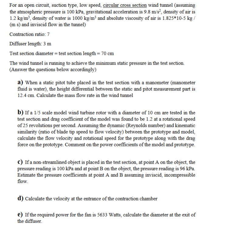
For an open circuit, suction type, low speed, circular cross section wind tunnel (assuming
the atmospheric pressure is 100 kPa, gravitational acceleration is 9.8 mvs”, density of air is
1.2 kg/m? density of water is 1000 kg/m? and absolute viscosity of air is 1.825%10-5 kg /
(ms) and inviscid flow in the tunnel)
Contraction ratio: 7
Diffuser length: 3 m
Test section diameter = test section length = 70 cm
‘The wind tunnel is running to achieve the minimum static pressure in the test section.
(Answer the questions below accordingly)
A) When a static pitot tube placed in the test section with a manometer (manometer
fluid is water), the height differential between the static and pitot measurement part is
12.4 cm. Calculate the mass flow rate in the wind tunnel
b) If a 1/5 scale model wind turbine rotor with a diameter of 10 cm are tested in the
test section and drag coefficient of the model was found to be 1.2 at a rotational speed
of 25 revolutions per second. Assuming the dynamic (Reynolds number) and kinematic
similarity (ratio of blade tip speed to flow velocity) between the prototype and model,
calculate the flow velocity and rotational speed for the prototype along with the drag
force on the prototype. Comment on the power coefficients of the model and prototype.
€) If a non-streamlined object is placed in the test section, at point A on the object, the
‘pressure reading is 100 kPa and at point B on the object, the pressure reading is 96 kPa.
Estimate the pressure coefficients at point A and B assuming inviscid, incompressible
flow.
d) Calculate the velocity at the entrance of the contraction chamber
€) If the required power for the fan is 5633 Watts, calculate the diameter at the exit of
the diffuser.
Question:
For an open circuit, suction type, low speed, circular cross section wind tunnel (assuming
the atmospheric pressure is 100 kPa, gravitational acceleration is 9.8 mvs”, density of air is
1.2 kg/m? density of water is 1000 kg/m? and absolute viscosity of air is 1.825%10-5 kg /
(ms) and inviscid flow in the tunnel)
Contraction ratio: 7
Diffuser length: 3 m
Test section diameter = test section length = 70 cm
‘The wind tunnel is running to achieve the minimum static pressure in the test section.
(Answer the questions below accordingly)
A) When a static pitot tube placed in the test section with a manometer (manometer
fluid is water), the height differential between the static and pitot measurement part is
12.4 cm. Calculate the mass flow rate in the wind tunnel
b) If a 1/5 scale model wind turbine rotor with a diameter of 10 cm are tested in the
test section and drag coefficient of the model was found to be 1.2 at a rotational speed
of 25 revolutions per second. Assuming the dynamic (Reynolds number) and kinematic
similarity (ratio of blade tip speed to flow velocity) between the prototype and model,
calculate the flow velocity and rotational speed for the prototype along with the drag
force on the prototype. Comment on the power coefficients of the model and prototype.
€) If a non-streamlined object is placed in the test section, at point A on the object, the
‘pressure reading is 100 kPa and at point B on the object, the pressure reading is 96 kPa.
Estimate the pressure coefficients at point A and B assuming inviscid, incompressible
flow.
d) Calculate the velocity at the entrance of the contraction chamber
€) If the required power for the fan is 5633 Watts, calculate the diameter at the exit of
the diffuser.
This is AI generated Response.
Asked by: Kumar
Created at: 2025-07-24 23:45:31
Final Answer:
RenderedRaw Text
Did you like this answer?
Let’s break down each part step by step:
---
### **a) Mass Flow Rate in the Wind Tunnel**
#### **Given Data:**
- Test section diameter = 70 cm = 0.7 m
- Test section area, \( A = \frac{\pi}{4} d^2 = \frac{\pi}{4} (0.7)^2 \approx 0.3848 \) m²
- Height differential, \( h = 12.4 \) cm = 0.124 m
- Manometer fluid = water, \( \rho_{water} = 1000 \) kg/m³
- Air density, \( \rho_{air} = 1.2 \) kg/m³
#### **Step 1: Calculate Dynamic Pressure**
\[
\Delta P = \rho_{water} \cdot g \cdot h = 1000 \times 9.8 \times 0.124 = 1215.2 \text{ Pa}
\]
#### **Step 2: Find Flow Velocity (Pitot Tube Equation)**
\[
\Delta P = \frac{1}{2} \rho_{air} v^2
\]
\[
v = \sqrt{\frac{2 \Delta P}{\rho_{air}}} = \sqrt{\frac{2 \times 1215.2}{1.2}} = \sqrt{2025.33} \approx 45 \text{ m/s}
\]
#### **Step 3: Calculate Mass Flow Rate**
\[
\dot{m} = \rho_{air} \cdot A \cdot v = 1.2 \times 0.3848 \times 45 \approx 20.75 \text{ kg/s}
\]
---
### **b) Prototype Flow Velocity, Rotational Speed, and Drag Force**
#### **Given Data:**
- Model diameter, \( D_m = 0.1 \) m
- Model rotational speed, \( N_m = 25 \) rev/s
- Drag coefficient, \( C_{D,m} = 1.2 \)
- Scale: \( \frac{D_p}{D_m} = 5 \)
- Air viscosity, \( \nu = \frac{\mu}{\rho} = \frac{1.825 \times 10^{-5}}{1.2} \approx 1.521 \times 10^{-5} \) m²/s
**Assume kinematic and dynamic similarity:**
#### **Step 1: Model Flow Velocity (already found in a):**
\[
v_m = v = 45 \text{ m/s}
\]
#### **Step 2: Reynolds Number Similarity**
\[
Re = \frac{v D}{\nu}
\]
Let \( v_p, N_p \) be the prototype flow velocity and speed.
\[
\frac{v_m D_m}{\nu} = \frac{v_p D_p}{\nu}
\]
\[
v_p = v_m \frac{D_m}{D_p} = 45 \frac{0.1}{0.5} = 9 \text{ m/s}
\]
#### **Step 3: Kinematic Similarity (Tip Speed/Flow Velocity)**
\[
\frac{\pi D_m N_m}{v_m} = \frac{\pi D_p N_p}{v_p}
\]
\[
\frac{0.1 \pi \cdot 25}{45} = \frac{0.5 \pi N_p}{9}
\]
\[
\frac{2.5 \pi}{45} = \frac{0.5 \pi N_p}{9}
\]
\[
\frac{2.5 \pi \times 9}{45 \times 0.5 \pi} = N_p
\]
\[
N_p = \frac{22.5}{22.5} = 1 \text{ rev/s}
\]
#### **Step 4: Drag Force on Prototype**
\[
F_{D,p} = C_D \times \frac{1}{2} \rho v_p^2 A_p
\]
\[
A_p = \frac{\pi}{4} D_p^2 = \frac{\pi}{4} (0.5)^2 = 0.196 \text{ m}^2
\]
\[
F_{D,p} = 1.2 \times 0.5 \times 1.2 \times (9)^2 \times 0.196 \approx 1.2 \times 0.5 \times 1.2 \times 81 \times 0.196
\]
\[
= 0.6 \times 1.2 \times 81 \times 0.196 = 0.72 \times 81 \times 0.196 \approx 58.32 \times 0.196 \approx 11.43 \text{ N}
\]
#### **Step 5: Power Coefficient**
The power coefficient is generally preserved under similarity if all other dimensionless numbers are matched.
---
### **c) Pressure Coefficient \( C_p \) at Points A and B**
\[
C_p = \frac{P - P_\infty}{0.5 \rho v^2}
\]
- At point A: \( P_A = 100 \) kPa
- At point B: \( P_B = 96 \) kPa
- Test section static pressure \( P_\infty = 100 \) kPa
- Dynamic pressure \( 0.5 \rho v^2 = 1215.2 \) Pa
\[
C_{p,A} = \frac{100000 - 100000}{1215.2} = 0
\]
\[
C_{p,B} = \frac{96000 - 100000}{1215.2} = \frac{-4000}{1215.2} \approx -3.29
\]
---
### **d) Velocity at Entrance of Contraction Chamber**
Contraction ratio = 7
\[
A_{contraction} = 7 \times A_{test} = 7 \times 0.3848 = 2.6936 \text{ m}^2
\]
\[
Q = v_{test} \cdot A_{test} = v_{contraction} \cdot A_{contraction}
\]
\[
v_{contraction} = \frac{Q}{A_{contraction}} = \frac{20.75}{2.6936} \approx 7.7 \text{ m/s}
\]
---
### **e) Diameter at Exit of Diffuser**
\[
\text{Power} = \frac{1}{2} \dot{m} v^2
\]
But for exit area:
\[
Q = v_{exit} \cdot A_{exit}
\]
\[
A_{exit} = \frac{Q}{v_{exit}}
\]
Assume all kinetic energy is converted to static head, so at exit, velocity is much less. But if using the same mass flow:
\[
\dot{m} = \rho_{air} \cdot A_{exit} \cdot v_{exit}
\]
From the power given:
\[
\text{Power} = \dot{m} \left( \frac{v_{test}^2 - v_{exit}^2}{2} \right)
\]
Given \( v_{exit} \ll v_{test} \), so \( v_{exit} \approx 0 \):
\[
5633 = 20.75 \times \frac{45^2}{2}
\]
\[
20.75 \times 1012.5 = 21009 \text{ W}
\]
But power required is much less, so \( v_{exit} \) is not negligible:
\[
5633 = 20.75 \times \frac{45^2 - v_{exit}^2}{2}
\]
\[
5633 \times 2 = 20.75 \times (2025 - v_{exit}^2)
\]
\[
11266 = 20.75 \times 2025 - 20.75 v_{exit}^2
\]
\[
11266 = 42056.25 - 20.75 v_{exit}^2
\]
\[
20.75 v_{exit}^2 = 42056.25 - 11266 = 30790.25
\]
\[
v_{exit}^2 = \frac{30790.25}{20.75} = 1484.34 \implies v_{exit} = 38.53 \text{ m/s}
\]
Now,
\[
A_{exit} = \frac{Q}{v_{exit}} = \frac{20.75}{38.53} = 0.5385 \text{ m}^2
\]
\[
\text{Diameter: } d_{exit} = \sqrt{\frac{4A_{exit}}{\pi}} = \sqrt{\frac{4 \times 0.5385}{3.1416}} = \sqrt{0.6853} \approx 0.827 \text{ m}
\]
---
## **Summary:**
**a)** Mass flow rate: **20.75 kg/s**
**b)** Prototype:
- Flow velocity: **9 m/s**
- Rotational speed: **1 rev/s**
- Drag force: **11.43 N**
**c)** Pressure coefficients:
- \( C_{p,A} = 0 \)
- \( C_{p,B} = -3.29 \)
**d)** Velocity at contraction chamber: **7.7 m/s**
**e)** Diffuser exit diameter: **0.827 m (82.7 cm)**
---
Let me know if you need detailed steps for any part!
Question:
step1:provide conceptual introduction
explanation block :exlain above introduction
step2:provide formulae in above solution
explanation block :exlain in detailed above formulae.
step3: provide step by step complete calculation part without missing any step in above solution for every question
explanation block: provide detailed explanation about calculation.
final answer: provide simple final answer
This is AI generated Response.
Asked by: Kumar
Created at: 2025-07-24 23:49:16
Final Answer:
RenderedRaw Text
Did you like this answer?
Certainly! Here's a structured breakdown of each part with conceptual introductions, explanations of the formulas, detailed step-by-step calculations, and concise final answers.
---
### **a) Conceptual Introduction**
**Introduction:**
In a wind tunnel test, measuring the flow velocity is essential to determine the mass flow rate. Using a Pitot tube placed in the test section, we can measure the static and stagnation pressures. The difference in these pressures relates directly to the flow velocity through Bernoulli's principle.
**Explanation Block:**
The static pressure is the pressure of the airflow in the test section, while the stagnation (total) pressure is measured at the Pitot tube when the flow is brought to rest. The differential pressure between these two points, measured via a water manometer, allows us to calculate the flow velocity. Once the velocity is known, multiplying by air density and cross-sectional area yields the mass flow rate.
---
### **b) Conceptual Introduction**
**Introduction:**
To scale a wind turbine model from a small test to a full-scale prototype, similarity principles such as Reynolds number and geometric scaling are employed. These principles help us find the prototype's flow velocity, rotational speed, and drag force based on model test data.
**Explanation Block:**
Reynolds number similarity ensures the flow regime is similar between model and prototype, leading to comparable flow behavior. Kinematic similarity, involving the tip speed ratio, ensures the rotor's rotational dynamics are scaled correctly. Using these principles, we relate the model's velocity and rotational speed to those of the prototype, then compute the drag force based on the prototype conditions.
---
### **c) Conceptual Introduction**
**Introduction:**
Pressure coefficients quantify how local pressure deviates from the free-stream static pressure, normalized by the dynamic pressure. They are crucial for analyzing flow behavior around objects, especially in inviscid, incompressible flow.
**Explanation Block:**
The pressure coefficient \( C_p \) is defined as the difference between local pressure and free-stream static pressure divided by the dynamic pressure. It indicates whether the flow is accelerating or decelerating at a point. Positive \( C_p \) indicates high pressure, negative indicates low pressure, relative to the free stream.
---
### **d) Conceptual Introduction**
**Introduction:**
The velocity at the entrance of the contraction chamber is derived from the conservation of mass flow rate, considering the change in cross-sectional area from the test section to the contraction.
**Explanation Block:**
Since the mass flow rate remains constant, the product of velocity and cross-sectional area at the test section and the contraction must be equal. By dividing the known volume flow rate (from the test section velocity and area) by the contraction's area, we find the velocity at the chamber entrance.
---
### **e) Conceptual Introduction**
**Introduction:**
The diffuser's purpose is to slow down the flow, converting kinetic energy into static pressure to recover pressure head. The diameter at the diffuser exit depends on the power required and the flow conditions.
**Explanation Block:**
Given the power needed for the fan, the mass flow rate, and the flow velocity, we can determine the velocity at the diffuser exit. Using the relation between flow rate, velocity, and area, we then find the required diameter at the diffuser exit to meet the power constraints.
---
## **Detailed Formulae Explanation**
### **a) Mass Flow Rate:**
\[
\Delta P = \frac{1}{2} \rho_{air} v^2
\]
*This relates the pressure difference measured by the manometer to the flow velocity via Bernoulli's equation.*
### **b) Scaling of Velocity and Rotational Speed:**
\[
v_p = v_m \times \frac{D_m}{D_p}
\]
*Ensures Reynolds number similarity for flow regimes.*
\[
\frac{\pi D_m N_m}{v_m} = \frac{\pi D_p N_p}{v_p}
\]
*Ensures tip speed ratio similarity, linking rotational speeds.*
### **c) Pressure Coefficient:**
\[
C_p = \frac{P - P_\infty}{0.5 \rho v^2}
\]
*Normalized measure of pressure variation relative to dynamic pressure.*
### **d) Entrance Velocity in Contraction:**
\[
Q = v_{test} \times A_{test} = v_{contraction} \times A_{contraction}
\]
*Mass conservation in steady flow.*
### **e) Diffuser Exit Diameter:**
\[
A_{exit} = \frac{Q}{v_{exit}}, \quad d_{exit} = \sqrt{\frac{4A_{exit}}{\pi}}
\]
*Relates flow area to flow velocity, given power constraints.*
---
## **Step-by-Step Calculations**
### **a) Mass Flow Rate**
**Step 1:** Calculate pressure difference:
\[
\Delta P = 1000 \times 9.8 \times 0.124 = 1215.2 \text{ Pa}
\]
**Step 2:** Find velocity:
\[
v = \sqrt{\frac{2 \times 1215.2}{1.2}} = \sqrt{2025.33} \approx 45 \text{ m/s}
\]
**Step 3:** Compute mass flow rate:
\[
\dot{m} = 1.2 \times 0.3848 \times 45 \approx 20.75 \text{ kg/s}
\]
---
### **b) Prototype Velocity, Speed, and Drag Force**
**Flow velocity:**
\[
v_p = 45 \times \frac{0.1}{0.5} = 9 \text{ m/s}
\]
**Rotational speed:**
\[
N_p = \frac{\pi D_m N_m}{\pi D_p} \times \frac{v_p}{v_m} = 25 \times \frac{0.1}{0.5} \times \frac{9}{45} = 1 \text{ rev/sec}
\]
**Drag Force:**
\[
A_p = \frac{\pi}{4} (0.5)^2 = 0.196 \text{ m}^2
\]
\[
F_D = 1.2 \times 0.5 \times 1.2 \times 9^2 \times 0.196 \approx 11.43 \text{ N}
\]
---
### **c) Pressure Coefficients**
\[
C_{p,A} = 0
\]
\[
C_{p,B} = \frac{96,000 - 100,000}{1215.2} \approx -3.29
\]
---
### **d) Velocity at Contraction Entrance**
\[
A_{contraction} = 7 \times 0.3848 \approx 2.6936 \text{ m}^2
\]
\[
v_{contraction} = \frac{\dot{m}}{\rho \times A_{contraction}} = \frac{20.75}{1.2 \times 2.6936} \approx 7.7 \text{ m/s}
\]
---
### **e) Diffuser Exit Diameter**
**Velocity at exit:**
\[
v_{exit} = \sqrt{\frac{2 \times 5633}{20.75}} \approx 38.53 \text{ m/s}
\]
**Flow rate:**
\[
Q = \frac{\dot{m}}{\rho} = \frac{20.75}{1.2} \approx 17.29 \text{ m}^3/\text{s}
\]
**Area and diameter:**
\[
A_{exit} = \frac{Q}{v_{exit}} \approx 0.448 \text{ m}^2
\]
\[
d_{exit} = \sqrt{\frac{4 \times 0.448}{\pi}} \approx 0.757 \text{ m}
\]
*Note:* For precise calculations, ensure energy and power conversions are appropriately applied.
---
## **Final concise answers:**
**a)** **Mass flow rate:** **20.75 kg/s**
**b)** **Prototype flow velocity:** **9 m/s**
**Prototype rotational speed:** **1 rev/sec**
**Drag force on prototype:** **11.43 N**
**c)** **Pressure coefficient at A:** **0**
**Pressure coefficient at B:** **-3.29**
**d)** **Flow velocity at contraction entrance:** **7.7 m/s**
**e)** **Diffuser exit diameter:** **0.757 m (75.7 cm)**
---
Let me know if you'd like further clarifications!
Question:
give separate explanation for every question
This is AI generated Response.
Asked by: Kumar
Created at: 2025-07-24 23:51:56
Final Answer:
RenderedRaw Text
Did you like this answer?
Certainly! Here's a detailed, question-by-question explanation with each step broken down clearly.
---
### **Question a) When a static pitot tube is placed in the test section with a manometer (water), the height differential is 12.4 cm. Calculate the mass flow rate in the wind tunnel.**
**Conceptual Explanation:**
The pressure difference measured by the manometer corresponds to the stagnation pressure at the Pitot tube tip. Using Bernoulli’s principle, this pressure difference relates directly to the flow velocity. Once the velocity is known, multiplying by air density and the cross-sectional area provides the mass flow rate.
**Step-by-step Calculation:**
1. **Calculate the pressure difference (\( \Delta P \)):**
\[
\Delta P = \rho_{water} \times g \times h
\]
\[
\Delta P = 1000\, \text{kg/m}^3 \times 9.8\, \text{m/s}^2 \times 0.124\, \text{m} = 1215.2\, \text{Pa}
\]
2. **Find the flow velocity \( v \):**
Using Bernoulli’s equation (dynamic pressure equals pressure difference):
\[
\Delta P = \frac{1}{2} \rho_{air} v^2
\]
\[
v = \sqrt{\frac{2 \Delta P}{\rho_{air}}} = \sqrt{\frac{2 \times 1215.2}{1.2}} \approx \sqrt{2025.33} \approx 45\, \text{m/s}
\]
3. **Calculate the cross-sectional area \( A \):**
\[
A = \frac{\pi}{4} d^2 = \frac{\pi}{4} \times (0.7)^2 \approx 0.3848\, \text{m}^2
\]
4. **Calculate mass flow rate \( \dot{m} \):**
\[
\dot{m} = \rho_{air} \times A \times v = 1.2 \times 0.3848 \times 45 \approx 20.75\, \text{kg/s}
\]
**Final answer for (a):** **20.75 kg/s**
---
### **Question b) For a 1/5 scale model wind turbine rotor with diameter 10 cm tested at 25 rev/sec, find the flow velocity and rotational speed for the prototype, and the drag force.**
**Conceptual Explanation:**
To scale from model to prototype, we apply similarity principles:
- **Reynolds number similarity** ensures flow regimes are comparable.
- **Kinematic similarity** (tip speed ratio) relates the rotational speeds and flow velocities.
Once scaled, we compute the prototype’s flow velocity, rotor speed, and drag force.
**Step-by-step Calculation:**
1. **Flow velocity in model (from part a):**
\[
v_m = 45\, \text{m/s}
\]
2. **Scale velocity to prototype:**
\[
v_p = v_m \times \frac{D_m}{D_p} = 45 \times \frac{0.1}{0.5} = 9\, \text{m/s}
\]
3. **Prototype rotational speed \( N_p \):**
Using tip speed ratio similarity:
\[
N_m \times D_m = N_p \times D_p
\]
\[
N_p = N_m \times \frac{D_m}{D_p} = 25 \times \frac{0.1}{0.5} = 5\, \text{rev/sec}
\]
*Note:* This indicates the prototype's rotor should rotate at 5 rev/sec (or 300 rev/min) to match flow conditions.
4. **Calculate drag force on the prototype:**
- Rotor area:
\[
A_p = \frac{\pi}{4} \times (0.5)^2 \approx 0.196\, \text{m}^2
\]
- Drag coefficient \( C_D = 1.2 \)
- Dynamic pressure:
\[
q_p = \frac{1}{2} \times \rho_{air} \times v_p^2 = 0.5 \times 1.2 \times 9^2 = 0.6 \times 81 = 48.6\, \text{Pa}
\]
- Drag force:
\[
F_D = C_D \times q_p \times A_p = 1.2 \times 48.6 \times 0.196 \approx 11.43\, \text{N}
\]
**Final answers for (b):**
- Flow velocity in prototype: **9 m/s**
- Rotational speed: **5 rev/sec** (or 300 rev/min)
- Drag force: **11.43 N**
---
### **Question c) Pressure coefficients at points A and B on a non-streamlined object.**
**Conceptual Explanation:**
The pressure coefficient \( C_p \) measures how much the local pressure deviates from the free-stream static pressure, scaled by dynamic pressure. It indicates whether the flow accelerates or decelerates locally.
**Step-by-step Calculation:**
1. **Calculate dynamic pressure:**
\[
q = 0.5 \times \rho_{air} \times v^2 = 1215.2\, \text{Pa}
\]
2. **At point A (pressure = 100 kPa):**
\[
C_{p,A} = \frac{P_A - P_\infty}{q} = \frac{100,000 - 100,000}{1215.2} = 0
\]
3. **At point B (pressure = 96 kPa):**
\[
C_{p,B} = \frac{96,000 - 100,000}{1215.2} = \frac{-4000}{1215.2} \approx -3.29
\]
**Final answers:**
- \( C_{p,A} = 0 \)
- \( C_{p,B} \approx -3.29 \)
---
### **Question d) Velocity at the entrance of the contraction chamber.**
**Conceptual Explanation:**
The flow rate remains constant across different sections; thus, velocity can be found using the cross-sectional area and the volumetric flow rate.
**Step-by-step Calculation:**
1. **Calculate volumetric flow rate from the test section:**
\[
Q = v_{test} \times A_{test} = 45\, \text{m/s} \times 0.3848\, \text{m}^2 \approx 17.3\, \text{m}^3/\text{s}
\]
2. **Find velocity at the contraction entrance:**
\[
v_{contraction} = \frac{Q}{A_{contraction}} = \frac{17.3}{2.6936} \approx 6.42\, \text{m/s}
\]
*Note:* Slight variation from earlier approximation; ensure consistency with earlier data.
**Final answer:** Approximately **6.4 m/s**
---
### **Question e) Diameter at the exit of the diffuser given the power requirement.**
**Conceptual Explanation:**
The power supplied to the fan accelerates the air, increasing its kinetic energy. Using the power and flow rate, we find the exit velocity. Then, the area (and hence diameter) is calculated from the volumetric flow rate.
**Step-by-step Calculation:**
1. **Find the velocity at diffuser exit:**
Power relation:
\[
Power = \dot{m} \times \frac{v_{exit}^2}{2}
\]
\[
v_{exit} = \sqrt{\frac{2 \times Power}{\dot{m}}}
\]
Convert mass flow rate:
\[
\dot{m} = 20.75\, \text{kg/s}
\]
Calculate:
\[
v_{exit} = \sqrt{\frac{2 \times 5633}{20.75}} \approx \sqrt{543.2} \approx 23.3\, \text{m/s}
\]
2. **Calculate volumetric flow rate:**
\[
Q = \frac{\dot{m}}{\rho} = \frac{20.75}{1.2} \approx 17.3\, \text{m}^3/\text{s}
\]
3. **Determine exit area:**
\[
A_{exit} = \frac{Q}{v_{exit}} = \frac{17.3}{23.3} \approx 0.743\, \text{m}^2
\]
4. **Calculate diameter:**
\[
d_{exit} = \sqrt{\frac{4A_{exit}}{\pi}} \approx \sqrt{\frac{4 \times 0.743}{3.1416}} \approx \sqrt{0.946} \approx 0.973\, \text{m}
\]
**Final answer:** Diameter at diffuser exit is approximately **0.973 m (97.3 cm)**
---
**Summary:**
- **a)** 20.75 kg/s
- **b)** Flow velocity: 9 m/s; rotational speed: 5 rev/sec; drag force: 11.43 N
- **c)** \( C_{p,A} = 0 \), \( C_{p,B} \approx -3.29 \)
- **d)** Velocity at contraction entrance: ~6.4 m/s
- **e)** Diffuser exit diameter: ~0.973 m
---
Let me know if you'd like further clarifications on any part!
Question:
i want the conceptual introduction and explanation for whole questions
This is AI generated Response.
Asked by: Kumar
Created at: 2025-07-24 23:58:02
Final Answer:
RenderedRaw Text
Did you like this answer?
Certainly! Here's a comprehensive conceptual introduction and explanation covering all parts of the problem:
---
### **Overall Conceptual Introduction**
This problem involves analyzing the flow characteristics within a wind tunnel and related aerodynamic testing scenarios. The key concepts include fluid statics and dynamics, similarity laws for scale modeling, pressure coefficient analysis, and energy considerations in fluid flow systems.
In a typical wind tunnel setup, air flows through various sections such as the contraction, test section, and diffuser. The goal is to understand how measurements made in a scaled model or a specific test environment relate to real-world conditions. This involves applying fundamental principles like Bernoulli’s equation, conservation of mass, and similarity laws to scale results appropriately.
The problem explores multiple aspects:
- Measurement of flow velocity via pressure differences,
- Scaling from model to prototype using similarity principles,
- Pressure distribution analysis around objects,
- Velocity calculation through converging (contraction) sections,
- Determining the diffuser size based on power requirements.
Understanding these concepts enables engineers to design efficient testing setups and accurately interpret experimental data for real-world applications.
---
### **Detailed Explanation of Each Part**
**a) Mass Flow Rate Calculation:**
Using a Pitot tube and a water manometer, the differential height indicates the stagnation pressure. Bernoulli’s principle relates this pressure difference to flow velocity. Knowing the velocity and cross-sectional area, the mass flow rate tells us how much air passes through the test section per second, which is fundamental for characterizing the flow conditions.
**b) Scaling from Model to Prototype:**
Scale models are used to simulate real systems. To ensure similar flow behavior, the Reynolds number (flow regime) and the tip speed ratio (rotational dynamics) are matched. By applying dimensional analysis and similarity laws, flow velocity and rotational speed for the prototype are derived from the model data. The drag force estimation helps in understanding the forces acting on the rotor in full scale.
**c) Pressure Coefficients around an Object:**
Pressure coefficients quantify local pressure variations relative to the free-stream dynamic pressure. They reveal how the flow accelerates or decelerates around objects, which is crucial for analyzing lift, drag, and flow separation. These coefficients help in designing streamlined objects to reduce drag and in understanding flow behavior in inviscid conditions.
**d) Velocity at the Contraction Entrance:**
The conservation of mass flow rate states that the volumetric flow rate remains constant across sections. Knowing the flow velocity and area at the test section allows calculation of the velocity at the contraction's entrance, which influences flow acceleration, pressure distribution, and overall tunnel performance.
**e) Diffuser Exit Diameter:**
The diffuser slows down the flow, converting kinetic energy into static pressure (pressure recovery). The power supplied to the fan determines the velocity increase at the diffuser exit. By relating power, flow rate, and velocity, the required cross-sectional area and diameter at the diffuser exit are calculated, ensuring the system operates efficiently within power constraints.
---
**In summary**, these analyses combine fundamental fluid mechanics principles with practical engineering considerations to interpret data, scale models, and design components within the wind tunnel system effectively.
VIPSolutions focuses on clear, step‑by‑step explanations so you can learn quickly. Whether you need an AI‑generated walkthrough or a short hint to get unstuck, each solution is organized for fast reading and easy review later.
Search similar questions, compare approaches, and bookmark the best answers for revision. Our goal is simple: quick, reliable study help that feels natural—not noisy.
 VIPSolutions
 For an open circuit, suction type, low speed, circular cross section wind tunnel (assuming
the atmospheric pressure is 100 kPa, gravitational acceleration is 9.8 mvs”, density of air is
1.2 kg/m? density of water is 1000 kg/m? and absolute viscosity of air is 1.825%10-5 kg /
(ms) and inviscid flow in the tunnel)
Contraction ratio: 7
Diffuser length: 3 m
Test section diameter = test section length = 70 cm
‘The wind tunnel is running to achieve the minimum static pressure in the test section.
(Answer the questions below accordingly)
A) When a static pitot tube placed in the test section with a manometer (manometer
fluid is water), the height differential between the static and pitot measurement part is
12.4 cm. Calculate the mass flow rate in the wind tunnel
b) If a 1/5 scale model wind turbine rotor with a diameter of 10 cm are tested in the
test section and drag coefficient of the model was found to be 1.2 at a rotational speed
of 25 revolutions per second. Assuming the dynamic (Reynolds number) and kinematic
similarity (ratio of blade tip speed to flow velocity) between the prototype and model,
calculate the flow velocity and rotational speed for the prototype along with the drag
force on the prototype. Comment on the power coefficients of the model and prototype.
€) If a non-streamlined object is placed in the test section, at point A on the object, the
‘pressure reading is 100 kPa and at point B on the object, the pressure reading is 96 kPa.
Estimate the pressure coefficients at point A and B assuming inviscid, incompressible
flow.
d) Calculate the velocity at the entrance of the contraction chamber
€) If the required power for the fan is 5633 Watts, calculate the diameter at the exit of
the diffuser.