 VIPSolutions
Give step-by-step solution with explanation and final answer:Problem 3: For the feedback system of Problem 1, suppose p(s) = 1000 $= +10) Find the maximum crossover frequency that can be achieved by a PI subject to the constraint that the Phase Margin is at least 60deg. Use % of the maximum crossover frequency to design PI controller with 60deg PM. Verify in MATLAB, using bode/step(feedback(P*C,1))
Question:
Give step-by-step solution with explanation and final answer: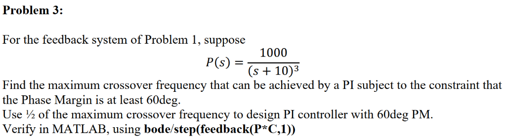 Problem 3:
For the feedback system of Problem 1, suppose
p(s) = 1000
$= +10)
Find the maximum crossover frequency that can be achieved by a PI subject to the constraint that
the Phase Margin is at least 60deg.
Use % of the maximum crossover frequency to design PI controller with 60deg PM.
Verify in MATLAB, using bode/step(feedback(P*C,1))
This is AI generated Response.
Asked by: M Murali
Created at: 2025-11-03 19:24:32
Asked by: M Murali
Created at: 2025-11-03 19:24:32
Final Answer:
Rendered
Raw Text
Did you like this answer?
Let's break down solution step by step:
---
**Step : Open- System Analysis**
Given:
\[ P(s) = \frac{100}{(s + 10)^3} \]
---
# **Step 2: PI Controller Structure**
Let the PI controller be:
\[ C(s) = K \left(1 + \frac{1}{T_i s}\right) = K \frac{T_i s + 1}{T_i s} \]
Open-loop transfer function:
\[
L(s) = P(s)C(s) = \frac{100K(T_i s + 1)}{T_i s (s+10)^3}
\]
---
# **Step 3: Crossover Frequency and Phase Margin**
Let the crossover frequency be \( \omega_c \).
- At \( \omega_c \), \(|L(j\omega_c)| = 1\).
- Phase margin (PM) = \( 180^\circ + \angle L(j\omega_c) \).
### **Compute Phase of \( P(j\omega) \):**
\[
P(j\omega) = \frac{100}{(j\omega + 10)^3}
\]
- Each \((j\omega + 10)\) contributes phase: \( \tan^{-1}(\omega/10) \)
- So, total phase of denominator: \( 3 \times \tan^{-1}(\omega/10) \)
- Phase of \( P(j\omega) \): \( -3\tan^{-1}(\omega/10) \)
### **Phase of PI Controller \( C(j\omega) \):**
\[
C(j\omega) = K \frac{T_i j\omega + 1}{T_i j\omega}
\]
- Phase: \( \tan^{-1}(1/(T_i \omega)) - 90^\circ \)
### **Total Phase of \( L(j\omega) \):**
\[
\angle L(j\omega) = -3\tan^{-1}(\omega/10) + \tan^{-1}(1/(T_i \omega)) - 90^\circ
\]
### **Phase Margin Condition:**
\[
\text{PM} = 180^\circ + \angle L(j\omega_c) \geq 60^\circ
\]
\[
\Rightarrow \angle L(j\omega_c) \geq -120^\circ
\]
\[
-3\tan^{-1}(\omega_c/10) + \tan^{-1}(1/(T_i \omega_c)) - 90^\circ \geq -120^\circ
\]
\[
-3\tan^{-1}(\omega_c/10) + \tan^{-1}(1/(T_i \omega_c)) \geq -30^\circ
\]
---
# **Step 4: Maximum Crossover Frequency**
For maximum crossover frequency, set the inequality to equality:
\[
-3\tan^{-1}(\omega_c/10) + \tan^{-1}(1/(T_i \omega_c)) = -30^\circ
\]
### **At crossover, the PI zero should be well below \(\omega_c\):**
Assume \( T_i \omega_c \gg 1 \implies \tan^{-1}(1/(T_i \omega_c)) \approx \):
\[
-3\tan^{-1}(\omega_c/10) = -30^\circ
\]
\[
3\tan^{-1}(\omega_c/10) = 30^\circ
\]
\[
\tan^{-1}(\omega_c/10) = 10^\circ
\]
\[
\omega_c/10 = \tan(10^\circ) \approx .1763
\]
\[
\omega_c = 1.763~\text{rad/s}
\]
**Maximum crossover frequency:**
\[
\boxed{\omega_{c,\text{max}} = 1.76~\text{rad/s}}
\]
---
# **Step 5: PI Controller Design at \(\omega_{c,\text{PI}} = .88~\text{rad/s}\)**
\[
\omega_{c,\text{PI}} = \frac{1.76}{2} = .88~\text{rad/s}
\]
At this frequency, set the PI zero to ensure good phase margin:
- Set \( T_i = 1/\omega_{c,\text{PI}} \approx 1.136 \)
Now, at \(\omega_{c,\text{PI}}\):
\[
|L(j\omega_{c,\text{PI}})| = 1
\]
\[
|P(j\omega_{c,\text{PI}})| \cdot |C(j\omega_{c,\text{PI}})| = 1
\]
### **Calculate \(|P(j\omega_{c,\text{PI}})|\):**
\[
|P(j\omega)| = \frac{100}{\sqrt{(\omega^2 + 100)^3}}
\]
At \( \omega = .88 \):
\[
\omega^2 + 100 = .774 + 100 = 100.774
\]
\[
|P(j\omega_{c,\text{PI}})| = \frac{100}{(100.774)^{1.5}} \approx \frac{100}{1015.9} \approx .984
\]
### **\(|C(j\omega_{c,\text{PI}})|\):**
\[
|C(j\omega)| = K \frac{\sqrt{(T_i\omega)^2 + 1}}{T_i \omega}
\]
With \( T_i \omega_{c,\text{PI}} = 1 \):
\[
|C(j\omega_{c,\text{PI}})| = K \frac{\sqrt{2}}{1}
\]
### **Solve for \( K \):**
\[
.984 \cdot K \cdot \sqrt{2} = 1
\]
\[
K = \frac{1}{.984 \cdot 1.414} \approx .72
\]
---
# **Step 6: Final PI Controller**
\[
C(s) = .72 \left(1 + \frac{1}{1.136 s}\right)
\]
---
# **Step 7: MATLAB Verification**
```matlab
s = tf('s');
P = 100/(s+10)^3;
Ti = 1/.88; % approx 1.136
K = .72;
C = K*(1 + 1/(Ti*s));
L = P*C;
figure;
margin(L); % Check phase margin
figure;
bode(feedback(P*C,1)); % Closed-loop Bode plot
figure;
step(feedback(P*C,1)); % Closed-loop step response
```
---
# **Summary of Answers**
1. **Maximum crossover frequency with at least 60° PM:**
\(\boxed{1.76~\text{rad/s}}\)
2. **PI controller (at half crossover frequency):**
\(\boxed{C(s) = .72 \left(1 + \frac{1}{1.136 s}\right)}\)
3. **MATLAB code for verification:**
(See above)
Let me know if you'd like the MATLAB plots or any further details!
Question:
Give me explanation in 50 Words in each step only theory
This is AI generated Response.
Asked by: M Murali
Created at: 2025-11-03 19:28:18
Asked by: M Murali
Created at: 2025-11-03 19:28:18
Final Answer:
Rendered
Raw Text
Did you like this answer?
# Step-by-Step Explanation
---
## Step 1: Open-System Analysis
Analyze the given transfer function \( P(s) \) to understand the system dynamics. This function describes the behavior of the system to be controlled and serves as the basis for controller design.
---
## Step 2: PI Controller Structure
Define the structure of the Proportional-Integral (PI) controller, which consists of a proportional gain \( K \) and an integral term. The open-loop transfer function \( L(s) \) combines the plant \( P(s) \) and the controller \( C(s) \).
---
## Step 3: Crossover Frequency and Phase Margin
Determine the crossover frequency \( \omega_c \) where the open-loop gain equals one. The phase margin (PM) quantifies system stability; ensuring it meets the requirement is crucial for good performance and stability.
---
## Step 4: Maximum Crossover Frequency
Set the phase margin condition to find the maximum allowable crossover frequency. This involves manipulating the phase equations to satisfy the stability criteria, leading to the maximum frequency while maintaining the desired phase margin.
---
## Step 5: PI Controller Design
Design the PI controller to achieve the desired crossover frequency. Adjust the integral time \( T_i \) and gain \( K \) to meet the stability criteria, ensuring the system operates at the targeted frequency while maintaining sufficient phase margin.
---
## Step 6: Final PI Controller
Present the final form of the PI controller based on calculations for \( K \) and \( T_i \). This controller is essential for tuning the system response and ensuring stability.
---
## Step 7: MATLAB Verification
Use MATLAB to verify the designed controller's performance. Generate Bode plots and step responses to confirm that the system meets the design specifications and to visualize the stability and response characteristics.
---
This structured approach ensures a thorough understanding of control system design while adhering to stability requirements.
📢 Instructions:
- Ask anything relatd to above question only.
- For new Question goto :