 VIPSolutions
Give step-by-step solution with explanation and final answer:econ (1 3) Ae cee EF $ “ied :
Question:
Give step-by-step solution with explanation and final answer: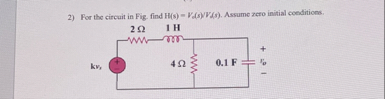 econ (1 3) Ae cee
EF $ “ied :
This is AI generated Response.
Asked by: M Murali
Created at: 2025-11-12 20:33:33
Asked by: M Murali
Created at: 2025-11-12 20:33:33
Final Answer:
Rendered
Raw Text
Did you like this answer?
Let's find the **transfer function** \( H(s) = \frac{V_o(s)}{V_g(s)} \) for the given circuit (with zero initial conditions).
---
## **Step 1: Label and Convert Components to s-domain**
- **2Ω Resistor:** \( 2 \Omega \) (unchanged)
- **1H Inductor:** \( sL = s \cdot 1 = s \Omega \)
- **4Ω Resistor:** \( 4 \Omega \) (unchanged)
- **.1F Capacitor:** \( \frac{1}{sC} = \frac{1}{s \cdot .1} = \frac{10}{s} \Omega \)
---
## **Step 2: Redraw in the s-domain**
```
+-----2Ω-----s-----+
| |
( ) [ ]
Vg 4Ω
| |
--- --- .1F
| |
GND ---
```
- The 4Ω and capacitor (\(\frac{10}{s}\)) are **in parallel**.
---
## **Step 3: Find Equivalent Impedance**
### **Parallel Combination:**
\[
Z_{eq} = \left( \frac{1}{4} + \frac{s}{10} \right)^{-1}
\]
\[
= \left( \frac{10 + 4s}{40} \right)^{-1}
= \frac{40}{10 + 4s}
\]
---
## **Step 4: Total Impedance**
\[
Z_{total} = 2 + s + Z_{eq}
= 2 + s + \frac{40}{10 + 4s}
\]
---
## **Step 5: Output Voltage Expression**
The output voltage \( V_o(s) \) is across the parallel branch.
By voltage divider:
\[
V_o(s) = V_g(s) \cdot \frac{Z_{eq}}{2 + s + Z_{eq}}
\]
\[
H(s) = \frac{V_o(s)}{V_g(s)} = \frac{Z_{eq}}{2 + s + Z_{eq}}
\]
\[
= \frac{\frac{40}{10 + 4s}}{2 + s + \frac{40}{10 + 4s}}
\]
---
## **Step 6: Simplify the Transfer Function**
Multiply numerator and denominator by \( (10 + 4s) \):
\[
H(s) = \frac{40}{(2 + s)(10 + 4s) + 40}
\]
Expand denominator:
\[
(2 + s)(10 + 4s) = 2 \times 10 + 2 \times 4s + s \times 10 + s \times 4s = 20 + 8s + 10s + 4s^2 = 20 + 18s + 4s^2
\]
Add 40:
\[
20 + 18s + 4s^2 + 40 = 60 + 18s + 4s^2
\]
So,
\[
H(s) = \frac{40}{4s^2 + 18s + 60}
\]
---
## **Final Answer**
\[
\boxed{
H(s) = \frac{V_o(s)}{V_g(s)} = \frac{40}{4s^2 + 18s + 60}
}
\]
---
**This is the transfer function for the circuit.**
Question:
Give ME Each Step 50 Words explanation only Theory
This is AI generated Response.
Asked by: M Murali
Created at: 2025-11-12 20:37:20
Asked by: M Murali
Created at: 2025-11-12 20:37:20
Final Answer:
Rendered
Raw Text
Did you like this answer?
# Transfer Function Derivation: Step-by-Step Explanation
## Step 1: Label and Convert Components
Identify the circuit components and convert them into the s-domain using Laplace transforms. Resistors remain unchanged, while inductors become \( sL \) and capacitors become \( \frac{1}{sC} \). This prepares the circuit for analysis in the frequency domain.
## Step 2: Redraw in the s-domain
Visualize the circuit in the s-domain, clearly showing the arrangement of components. This includes the series and parallel connections which will influence the impedance calculations and overall transfer function.
## Step 3: Find Equivalent Impedance
Calculate the equivalent impedance of the parallel components (4Ω resistor and capacitor). Use the formula for parallel resistors to derive a single impedance that simplifies further calculations in the circuit analysis.
## Step 4: Total Impedance
Determine the total impedance of the circuit by adding the series impedance of the 2Ω resistor, the inductor, and the equivalent impedance found in the previous step. This step is essential for finding the output voltage.
## Step 5: Output Voltage Expression
Express the output voltage \( V_o(s) \) across the parallel branch using a voltage divider rule. This helps to relate the output voltage to the input voltage \( V_g(s) \) in terms of the derived impedances, setting the stage for the transfer function.
## Step 6: Simplify the Transfer Function
Simplify the transfer function by multiplying through by the common denominator to eliminate fractions. Expand and combine like terms to obtain a standard polynomial form for easier interpretation and analysis of system behavior.
## Final Answer
The final transfer function \( H(s) \) provides a complete representation of the system's frequency response. This function can be used to analyze stability, frequency characteristics, and other dynamic behaviors of the electrical circuit.
📢 Instructions:
- Ask anything relatd to above question only.
- For new Question goto :