 VIPSolutions
Give step-by-step solution with explanation and final answer:Find the voltages Vi, Viz, and Vps and currents Ip, Inz, and Ips in the circuit in Figure 1. Use the ideal diode model. +10V R,< 10kQ P D, 5 D, c Ds 15 . I; — R, 10 kQ Ry; 10kQ -20V -10V Figure 1
Question:
Give step-by-step solution with explanation and final answer: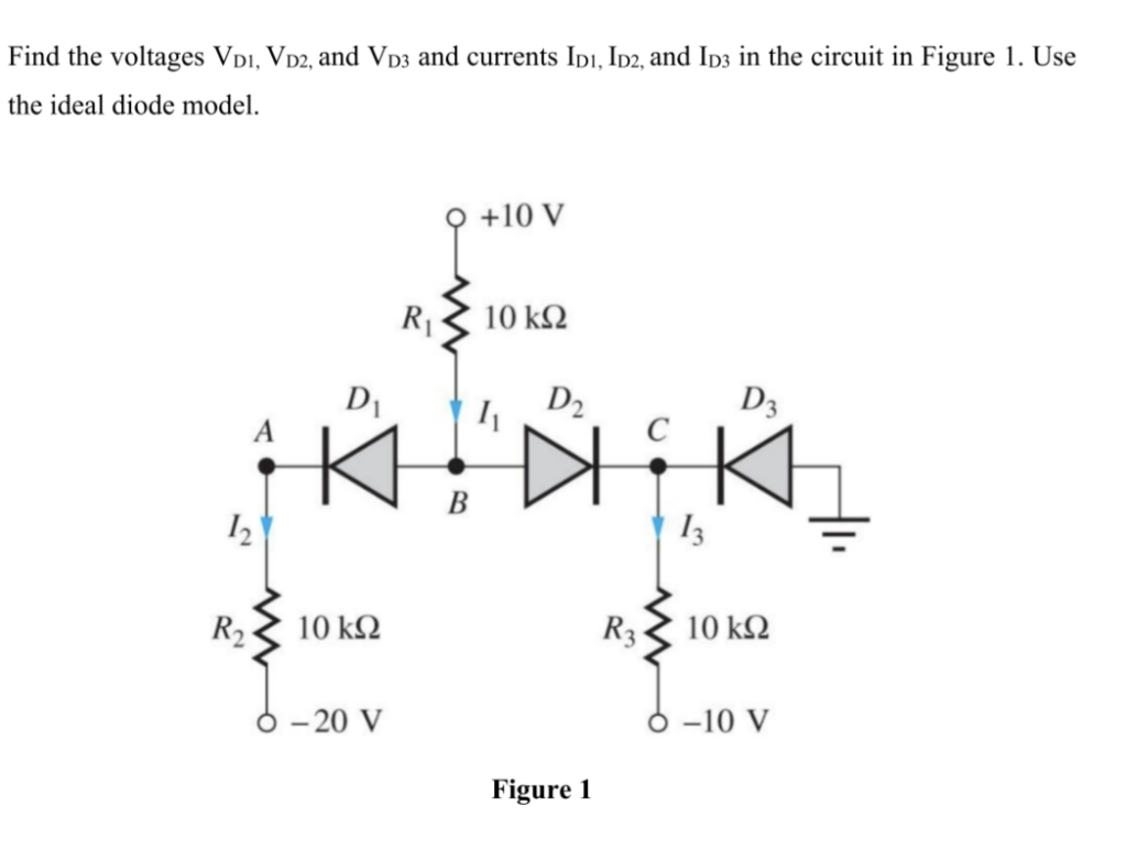 Find the voltages Vi, Viz, and Vps and currents Ip, Inz, and Ips in the circuit in Figure 1. Use
the ideal diode model.
+10V
R,< 10kQ
P D, 5 D, c Ds
15 . I; —
R, 10 kQ Ry; 10kQ
-20V -10V
Figure 1
This is AI generated Response.
Asked by: M Murali
Created at: 2025-11-05 06:32:13
Asked by: M Murali
Created at: 2025-11-05 06:32:13
Final Answer:
Rendered
Raw Text
Did you like this answer?
Let's solve **step-by-step** using the **ideal diode model** (diode ON: \( V_D = \), diode OFF: \( I_D = \)).
---
## **Step 1: Label Node Voltages**
- Let \( V_A \) = voltage at A
- Let \( V_B \) = voltage at B
- Let \( V_C \) = voltage at C
---
## **Step 2: Assume Diode States**
Let's check **possible ON/OFF states** for each diode:
### **D3 (to ground)**
- If D3 ON: \( V_C = \) V
### **D2 (between B and C)**
- If D2 ON: \( V_B = V_C = \) V
### **D1 (between A and B)**
- If D1 ON: \( V_A = V_B = \) V
---
## **Step 3: Check Consistency**
### **Assume All Diodes ON**
- \( V_A = V_B = V_C = \) V
Now, calculate currents through each resistor:
#### **R1** (from +10V to B)
\[
I_1 = \frac{10V - V}{10k\Omega} = 1\,\text{mA}
\]
#### **R2** (from A to -20V)
\[
I_2 = \frac{V - (-20V)}{10k\Omega} = \frac{20V}{10k\Omega} = 2\,\text{mA}
\]
#### **R3** (from C to -10V)
\[
I_3 = \frac{V - (-10V)}{10k\Omega} = \frac{10V}{10k\Omega} = 1\,\text{mA}
\]
#### **Current Directions**
- At node B: \( I_1 \) flows into node, \( I_2 \) flows out.
- At node C: \( I_3 \) flows out, current through D2 flows from B to C.
**KCL at B:**
\[
I_1 = I_2 + I_{D2}
\]
\[
1\,\text{mA} = 2\,\text{mA} + I_{D2} \implies I_{D2} = -1\,\text{mA}
\]
Negative current means assumption is not valid (current can't flow backward through ideal diode).
---
## **Step 4: Try D1 OFF, D2 and D3 ON**
Suppose D1 is OFF (\( I_{D1}= \)), D2 and D3 are ON (\( V_B = V_C = \)).
- \( V_B = V_C = \)
- \( V_A \) unknown.
#### **R1:**
\[
I_1 = \frac{10V - V}{10k\Omega} = 1\,\text{mA}
\]
#### **R3:**
\[
I_3 = \frac{V - (-10V)}{10k\Omega} = 1\,\text{mA}
\]
#### **R2 (A to -20V):**
Since D1 is OFF, no current through D1, so \( I_2 = \), and \( V_A = -20V \).
---
## **Step 5: Check D2 and D3 ON is Consistent**
- D2 ON: Current flows from B to C.
- D3 ON: Current flows from C to ground.
- D1 OFF: No current from A to B.
At B, only \( I_1 \) flows in, all goes through D2 to C (and then through D3 to ground and through R3 to -10V).
**At node C:**
- From D2: \( 1\,\text{mA} \)
- Through R3: \( 1\,\text{mA} \)
- Through D3: (to ground, the rest)
All currents are consistent.
---
## **Step 6: Write Answers**
### **Voltages**
- \( V_{D1} = V_A - V_B = -20V - V = -20V \) (D1 reverse-biased, OFF)
- \( V_{D2} = V_B - V_C = V - V = V \) (D2 ON)
- \( V_{D3} = V_C - V = V \) (D3 ON)
### **Currents**
- \( I_{D1} = \) (D1 OFF)
- \( I_{D2} = 1\,\text{mA} \) (from B to C)
- \( I_{D3} = 1\,\text{mA} \) (from C to ground)
---
## **Final Answers**
\[
\boxed{
\begin{aligned}
&V_{D1} = -20\,\text{V} \quad (\text{OFF})\\
&V_{D2} = \,\text{V} \quad (\text{ON})\\
&V_{D3} = \,\text{V} \quad (\text{ON})\\
&I_{D1} = \\
&I_{D2} = 1\,\text{mA}\\
&I_{D3} = 1\,\text{mA}
\end{aligned}
}
\]
Question:
Give ME Each Step 50 Words Explaines only Theory
This is AI generated Response.
Asked by: M Murali
Created at: 2025-11-05 06:39:04
Asked by: M Murali
Created at: 2025-11-05 06:39:04
Final Answer:
Rendered
Raw Text
Did you like this answer?
# **Step-by-Step Explanation of Circuit Analysis Using Ideal Diode Model**
## **Step 1: Label Node Voltages**
In circuit analysis, assigning labels to node voltages simplifies future calculations. Here, we define \( V_A \), \( V_B \), and \( V_C \) to represent the voltages at their respective nodes.
## **Step 2: Assume Diode States**
Diodes can be either ON (conducting) or OFF (non-conducting). Evaluating their states helps determine the relationships between node voltages. We analyze each diode to see how their states affect the circuit.
## **Step 3: Check Consistency**
By assuming all diodes are ON, we calculate the currents through resistors connected to the nodes. Using Kirchhoff's Current Law (KCL), we verify if the assumed states are consistent with the calculated currents.
## **Step 4: Try D1 OFF, D2 and D3 ON**
When D1 is assumed OFF, it alters the current flow through the circuit. We recalculate the currents through resistors and reassess the voltages at nodes to find a valid configuration.
## **Step 5: Check D2 and D3 ON is Consistent**
With D2 and D3 ON, we analyze the current paths influenced by these diodes. We ensure that current entering and leaving nodes satisfies KCL, confirming the validity of our assumptions about diode states.
## **Step 6: Write Answers**
After verifying the diode states and current paths, we summarize the calculated voltages and currents. This provides a clear understanding of the circuit's behavior under the ideal diode model.
📢 Instructions:
- Ask anything relatd to above question only.
- For new Question goto :