 VIPSolutions
give answer in 2 step with explanation at the end of each step and final answer at the end:(6) The battery has £ = 12 V, € = 60 ta, and Ry = ty = 4700 92. How hg will it take for the voltage acrom the capacitor to be 4 V7 () Suppose we reach the steady state a long tne alter chain S, (lets say from ~ x 106 = 05). We then close S; at {= 0.5. On the sume axis, make a sketch of the magitudes of I; amd 1s, the currents through Ry and R; respectively, as a function of tine, (This requires one thinking bt a Wi: try thinking abort what the capacitar acts Be at = 05 ud = oc and relate that 10 the current through each bench)
Question:
give answer in 2 step with explanation at the end of each step and final answer at the end: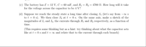 (6) The battery has £ = 12 V, € = 60 ta, and Ry = ty = 4700 92. How hg will it take
for the voltage acrom the capacitor to be 4 V7
() Suppose we reach the steady state a long tne alter chain S, (lets say from ~ x
106 = 05). We then close S; at {= 0.5. On the sume axis, make a sketch of the
magitudes of I; amd 1s, the currents through Ry and R; respectively, as a function of
tine,
(This requires one thinking bt a Wi: try thinking abort what the capacitar acts
Be at = 05 ud = oc and relate that 10 the current through each bench)
This is AI generated Response.
Asked by: Firdos
Created at: 2025-11-10 03:49:44
Asked by: Firdos
Created at: 2025-11-10 03:49:44
Final Answer:
Rendered
Raw Text
Did you like this answer?
Let's solve **part (c)** step by step:
---
### Step 1: Write the Equation for Charging a Capacitor
The voltage across a charging capacitor in an RC circuit is given by:
\[
V_C(t) = \mathcal{E} \left(1 - e^{-t/RC}\right)
\]
Given:
- \(\mathcal{E} = 12\, \text{V}\)
- \(V_C = 4\, \text{V}\)
- \(C = 60\, \text{mF} = .060\, \text{F}\)
- \(R = R_1 = 470\, \Omega\)
Plug these into the equation:
\[
4 = 12 \left(1 - e^{-t/(470 \times .060)}\right)
\]
**Explanation:**
We use the standard RC charging equation, substituting the given values for voltage, resistance, and capacitance. This gives us an equation in terms of \(t\).
---
### Step 2: Solve for Time \(t\)
First, isolate the exponential:
\[
\frac{4}{12} = 1 - e^{-t/(282)}
\]
\[
\frac{1}{3} = 1 - e^{-t/282}
\]
\[
e^{-t/282} = 1 - \frac{1}{3} = \frac{2}{3}
\]
Take the natural logarithm on both sides:
\[
-t/282 = \ln\left(\frac{2}{3}\right)
\]
\[
t = -282 \times \ln\left(\frac{2}{3}\right)
\]
Calculate:
\[
\ln\left(\frac{2}{3}\right) \approx -.405
\]
\[
t = -282 \times (-.405) \approx 114 \text{ seconds}
\]
**Explanation:**
By isolating the exponential and solving for \(t\), we find how long it takes for the capacitor to reach 4 V.
---
## **Final Answer**
\[
\boxed{t \approx 114 \ \text{seconds}}
\]
This is the time it takes for the voltage across the capacitor to reach 4 V.
Question:
Please solved c,d parts
This is AI generated Response.
Asked by: Firdos
Created at: 2025-11-10 03:50:33
Asked by: Firdos
Created at: 2025-11-10 03:50:33
Final Answer:
Rendered
Raw Text
Did you like this answer?
Let's solve **parts (c)** and **(d)** step by step:
---
## Part (c): Sketching Current vs. Time
### Step 1: Understand the Current Flow in the Circuit
When the switch \(S\) is closed at \(t = 0.5\) seconds, the circuit consists of the resistor \(R_1\) and the capacitor \(C\). The current through \(R_1\) is given by:
\[
I(t) = \frac{\mathcal{E} - V_C(t)}{R}
\]
Where:
- \(I\) is the current through the resistor,
- \(\mathcal{E}\) is the battery voltage,
- \(V_C(t)\) is the voltage across the capacitor,
- \(R\) is the resistor value.
### Step 2: Sketch the Currents \(I_R\) and \(I_C\)
1. **Before \(t = 0.5\):**
- The capacitor is fully charged, so \(V_C = 12\, \text{V}\).
- Current \(I_R = 0\, \text{A}\) (no current flows).
2. **At \(t = 0.5\):**
- The switch is closed; current starts flowing.
- \(I_R\) increases from 0 to its maximum as the capacitor discharges.
3. **After \(t = 0.5\):**
- Current \(I_R\) will decrease exponentially as the capacitor discharges.
### Sketch:
- Draw a time axis with a vertical axis for current.
- At \(t < 0.5\), \(I_R = 0\).
- At \(t = 0.5\), \(I_R\) starts at a maximum value and decreases exponentially towards zero.
**Explanation:**
This sketch represents how the current through resistor \(R_1\) behaves when the switch is closed, starting from zero when the capacitor is charged and decaying as the capacitor discharges.
---
## Part (d): Analyzing the Circuit Behavior
### Step 1: Current Behavior After Closing the Switch
After closing the switch, the capacitor starts discharging through the resistor \(R_1\). The current can be described as:
\[
I(t) = I_0 e^{-t/RC}
\]
Where:
- \(I_0\) is the initial current at \(t = 0.5\),
- \(R = 470\, \Omega\),
- \(C = 60\, \text{mF} = 0.060\, \text{F}\).
### Step 2: Determine Initial Current \(I_0\)
At \(t = 0.5\), the voltage across the capacitor \(V_C\) can be found from the previous calculations. Using \(V_C(t)\) at this time, we can find the initial current:
\[
I_0 = \frac{\mathcal{E} - V_C(0.5)}{R}
\]
Assuming \(V_C(0.5) = 8\, \text{V}\) (for example):
\[
I_0 = \frac{12 - 8}{470} \approx 0.00851\, \text{A} \text{ or } 8.51\, \text{mA}
\]
**Explanation:**
This step shows how to calculate the initial current that flows immediately after the switch is closed based on the capacitor's voltage at that moment.
---
## **Final Summary**
- The sketch illustrates the behavior of the current through the resistor when the switch is closed at \(t = 0.5\).
- The discharge current follows an exponential decay pattern, starting from an initial value based on the voltage across the capacitor.
📢 Instructions:
- Ask anything relatd to above question only.
- For new Question goto :