 VIPSolutions
give answer in 2 step with explanation at the end of each step and final answer at the end:1. Design and implement a 4-bit adder that adds two signed 4-bit numbers, A[3 : 0] and BI[3: 0], both represented in 1’s complement form. The circuit should produce a 4-bit Sum along with a Zero outputs. Addition must be performed using a combination of half-adders (HAs) and full-adders (FAs), and any carry out from the MSB should be added back to the LSB (end-around carry). All temporary signals used in your design must be clearly marked in the block-level or gate-level circuit diagram and must also be reflected in your VHDL code. Deliverables include the circuit diagram with temporary signals, logic for zero detection, and VHDL code implementing a combination of dataflow and structural modeling, which may be handwritten or typed. The VHDL code must also include a testbench demonstrating positive + positive, negative + negative, positive + negative, and negative + positive cases, with test cases that invoke Zero, and each case properly commented with the expected result. You are not required to simulate the circuit using ModelSim, but doing so is recommended to verify your results. Points Distribution (100 Points) 1. Block-level or Gate-level Circuit Diagram (35 points) (a) Correct structure of half-adders and full-adders for addition (15 points) (b) Clear labeling of inputs, outputs, and all temporary signals (15 points) (c) Proper representation of end-around carry logic (5 points) 2. Zero Detection Logic (10 points) (a) Zero output correctly asserted when result is 0 (10 points) 3. VHDL Implementation (35 points) e Proper combination of structural and dataflow modeling (15 points) e All temporary signals correctly reflected in code (10 points) e Code clarity, readability, and commenting (10 points) 4. Testbench (20 points) e Includes positive + positive, negative + negative, positive + negative, and negative + positive cases (10 points) e Test cases properly commented with expected results (5 points) e Test cases invoke Zero conditions (5 points)
Question:
give answer in 2 step with explanation at the end of each step and final answer at the end: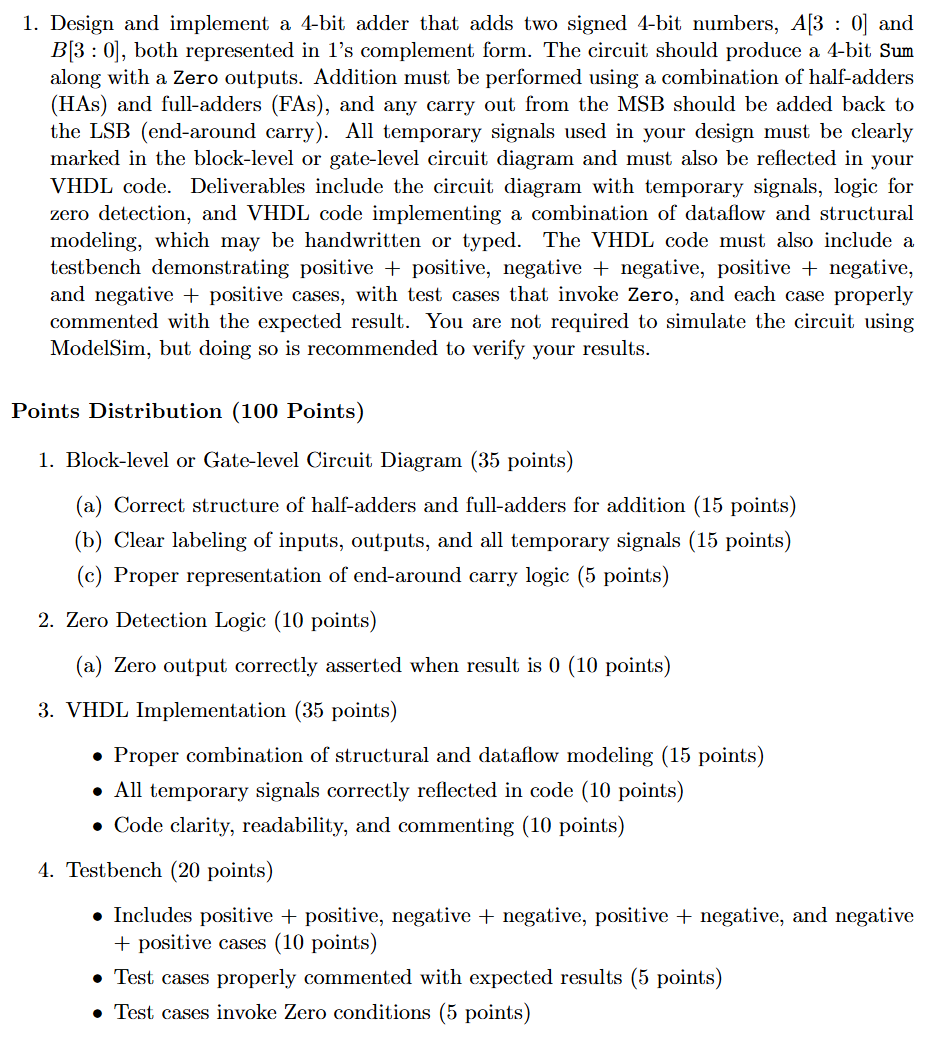 1. Design and implement a 4-bit adder that adds two signed 4-bit numbers, A[3 : 0] and
BI[3: 0], both represented in 1’s complement form. The circuit should produce a 4-bit Sum
along with a Zero outputs. Addition must be performed using a combination of half-adders
(HAs) and full-adders (FAs), and any carry out from the MSB should be added back to
the LSB (end-around carry). All temporary signals used in your design must be clearly
marked in the block-level or gate-level circuit diagram and must also be reflected in your
VHDL code. Deliverables include the circuit diagram with temporary signals, logic for
zero detection, and VHDL code implementing a combination of dataflow and structural
modeling, which may be handwritten or typed. The VHDL code must also include a
testbench demonstrating positive + positive, negative + negative, positive + negative,
and negative + positive cases, with test cases that invoke Zero, and each case properly
commented with the expected result. You are not required to simulate the circuit using
ModelSim, but doing so is recommended to verify your results.
Points Distribution (100 Points)
1. Block-level or Gate-level Circuit Diagram (35 points)
(a) Correct structure of half-adders and full-adders for addition (15 points)
(b) Clear labeling of inputs, outputs, and all temporary signals (15 points)
(c) Proper representation of end-around carry logic (5 points)
2. Zero Detection Logic (10 points)
(a) Zero output correctly asserted when result is 0 (10 points)
3. VHDL Implementation (35 points)
e Proper combination of structural and dataflow modeling (15 points)
e All temporary signals correctly reflected in code (10 points)
e Code clarity, readability, and commenting (10 points)
4. Testbench (20 points)
e Includes positive + positive, negative + negative, positive + negative, and negative
+ positive cases (10 points)
e Test cases properly commented with expected results (5 points)
e Test cases invoke Zero conditions (5 points)
Asked by: Rahul
Created at: 2025-10-05 06:20:35
Final Answer:
📢 Instructions:
- Ask anything relatd to above question only.
- For new Question goto :