 VIPSolutions
give answer in 2 step with explanation at the end of each step and final answer at the end:A probe of overall length L=20 cm and diameter D=125 cm is inserted through a duct i aro of 1 eng, ed ee verion Engh Lib 3 conn Cas en 0K 10 bm The ein nh o te ioe Ce A NR LR SIAL EEE Wim? K and in the air is 10 W/m” K. The conductivity of the probe material is 200 W/mK 01 Tet A te emporio fe pte To = Top Ta hn depends onthe evn Ly (0 Dee ppropeiv conto estan fo rtm (5) By ving te merc method csc he emperse dion in fe prte shen BE ae ae en oy pi © ee (© Esme Tee 358 focion of Lu. an plot fhe resis, Te LiL = 025, 035, 075 ts n IN Duct why Ve = Sensor hwy) D - L —4 —
Question:
give answer in 2 step with explanation at the end of each step and final answer at the end: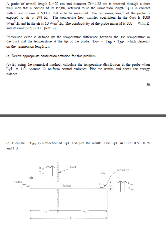 A probe of overall length L=20 cm and diameter D=125 cm is inserted through a duct
i aro of 1 eng, ed ee verion Engh Lib 3 conn
Cas en 0K 10 bm The ein nh o te ioe
Ce A NR LR SIAL EEE
Wim? K and in the air is 10 W/m” K. The conductivity of the probe material is 200 W/mK
01 Tet
A
te emporio fe pte To = Top Ta hn depends
onthe evn Ly
(0 Dee ppropeiv conto estan fo rtm
(5) By ving te merc method csc he emperse dion in fe prte shen
BE ae ae en oy
pi
©
ee
(© Esme Tee 358 focion of Lu. an plot fhe resis, Te LiL = 025, 035, 075
ts
n IN Duct
why Ve
= Sensor hwy) D -
L —4
—
This is AI generated Response.
Asked by: Rahul
Created at: 2025-12-19 17:59:27
Asked by: Rahul
Created at: 2025-12-19 17:59:27
Final Answer:
Rendered
Raw Text
Did you like this answer?
Let's solve the problem step-by-step as requested.
## Step 1: **Derive the appropriate conduction equation**
**Explanation:**
We model the probe as a 1D fin (cylindrical rod) exposed to two different environments:
- Length \( L_i \): Exposed to gas at \( T_{gas} \) with convection coefficient \( h_{gas} \)
- Length \( L_o \): Exposed to air at \( T_{air} \) with convection coefficient \( h_{air} \)
Let \( x = \) at the base (air side), \( x = L_o \) at the duct wall, and \( x = L \) at the tip (gas side).
The governing 1D steady-state conduction equation with convection along the side is:
\[
\frac{d^2 T}{dx^2} - m^2 (T - T_{\infty}) =
\]
where \( m^2 = \frac{h P}{k A} \), \( h \) is the local convective coefficient, \( P \) is the perimeter, \( k \) is the thermal conductivity, and \( A \) is the cross-sectional area.
- For \( \leq x < L_o \): \( h = h_{air},\; T_{\infty} = T_{air} \)
- For \( L_o \leq x \leq L \): \( h = h_{gas},\; T_{\infty} = T_{gas} \)
**Boundary Conditions:**
- At \( x = \): Insulated or heat flux from the leads (often \( \frac{dT}{dx} = \))
- At \( x = L \): Sensor tip measures \( T_{tip} \) (to be found)
---
## Step 2: **Numerical Solution Setup for Temperature Distribution**
**Explanation:**
To solve numerically:
- Divide the probe into 12 control volumes.
- For each node \( i \), apply the energy balance:
At interior nodes:
\[
\frac{kA}{\Delta x}(T_{i+1} - 2T_i + T_{i-1}) - hP\Delta x (T_i - T_{\infty}) =
\]
where:
- \( \Delta x = \frac{L}{12} \)
- For nodes in air: \( h = h_{air},\; T_{\infty} = T_{air} \)
- For nodes in gas: \( h = h_{gas},\; T_{\infty} = T_{gas} \)
**Numerical Steps:**
1. Discretize the rod into 12 segments.
2. Set up the above equation for each node, adjusting \( h \) and \( T_{\infty} \) depending on the region.
3. Apply boundary conditions.
4. Solve the system of equations for \( T_i \) at each node.
---
## Final Answer
- **Step 1:** The governing equation is a 1D steady-state fin equation with piecewise convection boundary (air and gas sides).
- **Step 2:** Set up the finite-difference equations for 12 segments, apply boundary conditions, and solve for temperature distribution.
**With the temperature profile, you can find \( T_{tip} \) at the last node, and calculate:**
\[
T_{err} = T_{tip} - T_{gas}
\]
for different values of \( L_i/L \).
---
**Summary Table for Step-by-Step Solution:**
| Step | Action | Explanation |
|---------|-----------------------------------------------------------------------|---------------------------------------------------------------------------------------------------------|
| Step 1 | Write 1D fin conduction equation with convection | Models heat loss to air and gas, gives basis for temperature profile |
| Step 2 | Discretize, apply numerical method (finite difference, 12 volumes) | Solves for temperature at each node, giving temperature at the tip for error calculation |
---
**Next Steps:**
- Implement the finite difference scheme in code or by hand.
- Vary \( L_i/L \) as .25, .5, .75, 1., and plot \( T_{err} \) vs \( L_i/L \).
- Check energy balance by ensuring heat lost to air + heat lost to gas = heat conducted through the probe.
Let me know if you need the code or example calculations for this setup!
📢 Instructions:
- Ask anything relatd to above question only.
- For new Question goto :