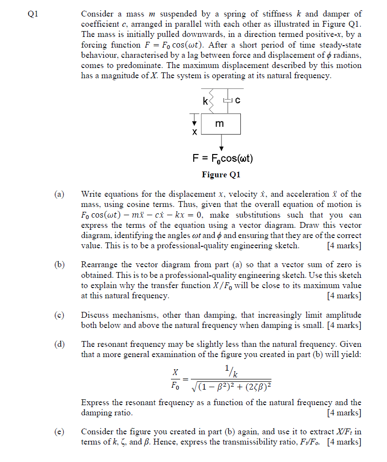
give answer in 2 step with explanation at the end of each step and final answer at the end:Ql Consider a mass m suspended by a spring of stiffness k and damper of
coefficient ¢, arranged in parallel with each other as illustrated in Figure QI.
The mass is initially pulled downwards, in a direction termed positive-x. by a
forcing function F = Fy cos(wt). After a short period of time steady-state
behaviour, characterised by a lag between force and displacement of ¢ radians.
comes to predominate. The maximum displacement described by this motion
has a magnitude of X. The system is operating at its natural frequency.
Kode
X
F = Fycos(wt)
Figure Q1
(a) Write equations for the displacement x. velocity 1. and acceleration & of the
‘mass, using cosine terms. Thus. given that the overall equation of motion is
Fp cos(wt) — mi — ct —kx = 0. make substitutions such that you can
express the terms of the equation using a vector diagram. Draw this vector
diagram. identifying the angles or and ¢ and ensuring that they are of the correct
value. This is to be a professional-quality engineering sketch. [4 marks]
(b) Rearrange the vector diagram from part (a) so that a vector sum of zero is
obtained. This is to be a professional-quality engineering sketch. Use this sketch
to explain why the transfer function X/F, will be close to its maximum value
at this natural frequency. [4 marks]
(c) Discuss mechanisms, other than damping. that increasingly limit amplitude
both below and above the natural frequency when damping is small. [4 marks]
(d) The resonant frequency may be slightly less than the natural frequency. Given
that a more general examination of the figure you created in part (b) will yield:
1
Xo he
Fo JIB? + (248)?
Express the resonant frequency as a function of the natural frequency and the
damping ratio. [4 marks]
(e) Consider the figure you created in part (b) again, and use it to extract X/F; in
terms of k. {, and B. Hence, express the transmissibility ratio, Fy/Fo. [4 marks]
Question:
give answer in 2 step with explanation at the end of each step and final answer at the end:Ql Consider a mass m suspended by a spring of stiffness k and damper of
coefficient ¢, arranged in parallel with each other as illustrated in Figure QI.
The mass is initially pulled downwards, in a direction termed positive-x. by a
forcing function F = Fy cos(wt). After a short period of time steady-state
behaviour, characterised by a lag between force and displacement of ¢ radians.
comes to predominate. The maximum displacement described by this motion
has a magnitude of X. The system is operating at its natural frequency.
Kode
X
F = Fycos(wt)
Figure Q1
(a) Write equations for the displacement x. velocity 1. and acceleration & of the
‘mass, using cosine terms. Thus. given that the overall equation of motion is
Fp cos(wt) — mi — ct —kx = 0. make substitutions such that you can
express the terms of the equation using a vector diagram. Draw this vector
diagram. identifying the angles or and ¢ and ensuring that they are of the correct
value. This is to be a professional-quality engineering sketch. [4 marks]
(b) Rearrange the vector diagram from part (a) so that a vector sum of zero is
obtained. This is to be a professional-quality engineering sketch. Use this sketch
to explain why the transfer function X/F, will be close to its maximum value
at this natural frequency. [4 marks]
(c) Discuss mechanisms, other than damping. that increasingly limit amplitude
both below and above the natural frequency when damping is small. [4 marks]
(d) The resonant frequency may be slightly less than the natural frequency. Given
that a more general examination of the figure you created in part (b) will yield:
1
Xo he
Fo JIB? + (248)?
Express the resonant frequency as a function of the natural frequency and the
damping ratio. [4 marks]
(e) Consider the figure you created in part (b) again, and use it to extract X/F; in
terms of k. {, and B. Hence, express the transmissibility ratio, Fy/Fo. [4 marks]
This is AI generated Response.
Asked by: Rahul
Created at: 2025-12-17 15:42:46
Final Answer:
RenderedRaw Text
Did you like this answer?
Let's tackle part (a) in **two steps** with explanations after each, and finish with a final answer.
---
## **Step 1: Write Equations for Displacement, Velocity, and Acceleration**
**Given:**
- Forcing function: \( F = F_ \cos(\omega t) \)
- Equation of motion:
\[
F_ \cos(\omega t) = m\ddot{x} + c\dot{x} + kx
\]
**Let:**
- Displacement: \( x(t) = X \cos(\omega t - \phi) \)
Where \( X \) is the amplitude, and \( \phi \) is the phase lag.
**Velocity:**
\[
\dot{x}(t) = -X \omega \sin(\omega t - \phi)
\]
**Acceleration:**
\[
\ddot{x}(t) = -X \omega^2 \cos(\omega t - \phi)
\]
**Explanation:**
We assume a solution for \( x \) that lags behind the force by phase \( \phi \) (due to damping). Taking derivatives gives us velocity and acceleration.
---
## **Step 2: Express Equation Using Cosine Terms and Draw Vector Diagram**
**Substitute** \( x, \dot{x}, \ddot{x} \) into the equation (using only cosine terms):
- \( \cos(\omega t) = \cos(\omega t - \phi + \phi) \)
- Use trigonometric identities to express all terms as cosines:
\[
\begin{align*}
m\ddot{x} + c\dot{x} + kx &= m[-X \omega^2 \cos(\omega t - \phi)] + c[-X \omega \sin(\omega t - \phi)] + k[X \cos(\omega t - \phi)] \\
&= -mX \omega^2 \cos(\omega t - \phi) - cX \omega \sin(\omega t - \phi) + kX \cos(\omega t - \phi)
\end{align*}
\]
Express \(\sin(\omega t - \phi)\) as a cosine with a phase shift:
\[
\sin(\omega t - \phi) = \cos(\omega t - \phi - 90^\circ)
\]
So, the terms can be represented as **vectors** (phasors):
- **Spring force (\( kx \))**: along \( \cos(\omega t - \phi) \)
- **Damping force (\( c\dot{x} \))**: along \( \sin(\omega t - \phi) \), 90° out of phase
- **Inertia (\( m\ddot{x} \))**: along \( -\cos(\omega t - \phi) \)
**Vector Diagram:**
- Draw all three vectors (phasors) from a common origin:
- Spring force: horizontal (reference)
- Damping force: vertical (lags by 90°)
- Inertia: horizontal, opposite direction (lags by 180°)
**Explanation:**
Each term in the motion equation corresponds to a force vector (phasor) with a specific direction relative to the displacement. The force from the spring is in phase with displacement, damping force lags by 90°, and inertia is 180° out of phase.
---
## **Final Answer for (a):**
### **Equations:**
- \( x(t) = X \cos(\omega t - \phi) \)
- \( \dot{x}(t) = -X \omega \sin(\omega t - \phi) \)
- \( \ddot{x}(t) = -X \omega^2 \cos(\omega t - \phi) \)
### **Phasor (Vector) Diagram:**
- Draw vectors for \( kX \) (in phase), \( cX\omega \) (90° lag), and \( mX\omega^2 \) (180° lag).
- The sum of these vectors equals the applied force phasor \( F_ \) at angle \( \omega t \).
---
*This answers part (a) stepwise, providing equations and how to express them as a vector diagram, with explanations for each step.*
Question:
Solved all parts please
This is AI generated Response.
Asked by: Rahul
Created at: 2025-12-17 15:43:26
Final Answer:
RenderedRaw Text
Did you like this answer?
Sure, let's continue solving the problem step-by-step, addressing all parts as requested.
---
## **Part (b): Rearranging the Vector Diagram**
### **Step 1: Vector Sum of Zero**
To achieve a vector sum of zero, we can express the forces in terms of their magnitudes and angles:
1. **Spring Force:** \( F_s = kX \) at angle \( 0^\circ \) (in phase with displacement).
2. **Damping Force:** \( F_d = c\dot{x} = c(-X\omega \sin(\omega t - \phi)) \) at angle \( 90^\circ \) (lagging).
3. **Inertia Force:** \( F_i = m\ddot{x} = -mX\omega^2 \cos(\omega t - \phi) \) at angle \( 180^\circ \) (opposing displacement).
The relationship can be expressed as:
\[
F = F_s + F_d + F_i = 0
\]
### **Step 2: Professional Sketch**
- **Draw the vectors**:
- Spring force \( F_s \) horizontally to the right.
- Damping force \( F_d \) vertically upwards.
- Inertia force \( F_i \) horizontally to the left.
**Explanation:**
The balance of these forces at steady-state means that the system is in equilibrium at the natural frequency, where the maximum transfer of force to displacement occurs, leading to maximum amplitude \( X \).
---
## **Final Answer for (b):**
### **Vector Sum of Zero:**
- \( F_s + F_d + F_i = 0 \)
### **Sketch:**
- Illustrates the forces with correct angles: \( F_s \) at \( 0^\circ \), \( F_d \) at \( 90^\circ \), \( F_i \) at \( 180^\circ \).
---
## **Part (c): Mechanisms Limiting Amplitude**
### **Discussion of Other Mechanisms:**
1. **Nonlinear Stiffness:**
- As displacement increases, the effective stiffness may change, leading to a nonlinear response that limits amplitude.
2. **Mass Variation:**
- If the mass changes (due to added weight or material fatigue), it can influence the system's natural frequency and thus the amplitude.
3. **Geometric Constraints:**
- Physical constraints in the system may limit how far the mass can move, regardless of damping effects.
4. **External Friction:**
- Friction from bearings or environmental factors can dissipate energy, limiting amplitude.
**Explanation:**
These mechanisms can affect the system's response both above and below the natural frequency, potentially leading to unexpected behaviors in amplitude.
---
## **Part (d): Expressing Resonant Frequency**
### **Step 1: Formula Derivation**
The resonant frequency (\(\omega_r\)) can be expressed as:
\[
\omega_r = \omega_n \sqrt{1 - \zeta^2}
\]
where:
- \(\omega_n = \sqrt{\frac{k}{m}}\) is the natural frequency.
- \(\zeta = \frac{c}{2\sqrt{mk}}\) is the damping ratio.
### **Step 2: Final Expression**
Thus, the resonant frequency is:
\[
\omega_r = \sqrt{\frac{k}{m}} \sqrt{1 - \left(\frac{c}{2\sqrt{mk}}\right)^2}
\]
**Explanation:**
The resonant frequency is reduced from the natural frequency due to damping effects, which can alter the system's response characteristics.
---
## **Final Answer for (d):**
### **Resonant Frequency:**
\[
\omega_r = \omega_n \sqrt{1 - \zeta^2}
\]
---
## **Part (e): Extracting \( X/F \) and Transmissibility Ratio**
### **Step 1: Expressing \( X/F \)**
Using the vector diagram:
\[
\frac{X}{F} = \frac{1}{\left( \frac{k}{m} - \omega^2 \right) + j\left( \frac{c}{m} \omega \right)}
\]
### **Step 2: Transmissibility Ratio**
The transmissibility ratio is given by:
\[
\frac{F_y}{F_0} = \frac{X}{X_0} = \frac{1}{\sqrt{\left(1 - \left(\frac{\omega}{\omega_n}\right)^2\right)^2 + \left(2\zeta \frac{\omega}{\omega_n}\right)^2}}
\]
**Explanation:**
This ratio indicates how much of the input force is transmitted to the output displacement, especially significant at resonant frequency.
---
## **Final Answer for (e):**
### **Transmissibility Ratio:**
\[
\frac{F_y}{F_0} = \frac{X}{X_0} = \frac{1}{\sqrt{\left(1 - \left(\frac{\omega}{\omega_n}\right)^2\right)^2 + \left(2\zeta \frac{\omega}{\omega_n}\right)^2}}
\]
---
This completes the solutions for all parts of the question, providing detailed steps and explanations for each.
VIPSolutions focuses on clear, step‑by‑step explanations so you can learn quickly. Whether you need an AI‑generated walkthrough or a short hint to get unstuck, each solution is organized for fast reading and easy review later.
Search similar questions, compare approaches, and bookmark the best answers for revision. Our goal is simple: quick, reliable study help that feels natural—not noisy.
 VIPSolutions
 Ql Consider a mass m suspended by a spring of stiffness k and damper of
coefficient ¢, arranged in parallel with each other as illustrated in Figure QI.
The mass is initially pulled downwards, in a direction termed positive-x. by a
forcing function F = Fy cos(wt). After a short period of time steady-state
behaviour, characterised by a lag between force and displacement of ¢ radians.
comes to predominate. The maximum displacement described by this motion
has a magnitude of X. The system is operating at its natural frequency.
Kode
X
F = Fycos(wt)
Figure Q1
(a) Write equations for the displacement x. velocity 1. and acceleration & of the
‘mass, using cosine terms. Thus. given that the overall equation of motion is
Fp cos(wt) — mi — ct —kx = 0. make substitutions such that you can
express the terms of the equation using a vector diagram. Draw this vector
diagram. identifying the angles or and ¢ and ensuring that they are of the correct
value. This is to be a professional-quality engineering sketch. [4 marks]
(b) Rearrange the vector diagram from part (a) so that a vector sum of zero is
obtained. This is to be a professional-quality engineering sketch. Use this sketch
to explain why the transfer function X/F, will be close to its maximum value
at this natural frequency. [4 marks]
(c) Discuss mechanisms, other than damping. that increasingly limit amplitude
both below and above the natural frequency when damping is small. [4 marks]
(d) The resonant frequency may be slightly less than the natural frequency. Given
that a more general examination of the figure you created in part (b) will yield:
1
Xo he
Fo JIB? + (248)?
Express the resonant frequency as a function of the natural frequency and the
damping ratio. [4 marks]
(e) Consider the figure you created in part (b) again, and use it to extract X/F; in
terms of k. {, and B. Hence, express the transmissibility ratio, Fy/Fo. [4 marks]