give answer in 2 step with explanation at the end of each step and final answer at the end:7 3
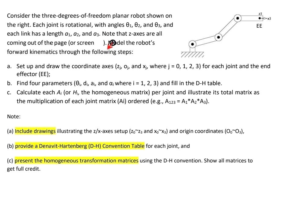
Consider the three-degrees-of-freedom planar robot shown on (8) ekw
the right. Each joint is rotational, with angles 61, 82, and 63, and EE
each link has a length a1, a, and as. Note that z-axes are all a
coming out of the page (or screen ) [Bel the robot's Gg =
forward kinematics through the following steps: TI
a. Setup and draw the coordinate axes (z, oj, and x;, where j = 0, 1, 2, 3) for each joint and the end
effector (EE);
b. Find four parameters (8;, d;, a, and ai where i = 1, 2, 3) and fill in the D-H table.
c. Calculate each A; (or Hi, the homogeneous matrix) per joint and illustrate its total matrix as
the multiplication of each joint matrix (Ai) ordered (e.g., A123 = A1*A2*A3).
Note:
(a) Include drawings illustrating the z/x-axes setup (202; and x,™x:) and origin coordinates (050s),
(5) provide a DenvitHartenberg (0-+) Convention Table fo each it, and
(c) using the D-H convention. Show all matrices to
get full credit.
Question:
give answer in 2 step with explanation at the end of each step and final answer at the end:7 3
Consider the three-degrees-of-freedom planar robot shown on (8) ekw
the right. Each joint is rotational, with angles 61, 82, and 63, and EE
each link has a length a1, a, and as. Note that z-axes are all a
coming out of the page (or screen ) [Bel the robot's Gg =
forward kinematics through the following steps: TI
a. Setup and draw the coordinate axes (z, oj, and x;, where j = 0, 1, 2, 3) for each joint and the end
effector (EE);
b. Find four parameters (8;, d;, a, and ai where i = 1, 2, 3) and fill in the D-H table.
c. Calculate each A; (or Hi, the homogeneous matrix) per joint and illustrate its total matrix as
the multiplication of each joint matrix (Ai) ordered (e.g., A123 = A1*A2*A3).
Note:
(a) Include drawings illustrating the z/x-axes setup (202; and x,™x:) and origin coordinates (050s),
(5) provide a DenvitHartenberg (0-+) Convention Table fo each it, and
(c) using the D-H convention. Show all matrices to
get full credit.
This is AI generated Response.
Asked by: Rahul
Created at: 2025-12-14 03:24:20
Final Answer:
RenderedRaw Text
Did you like this answer?
Sure! Let's proceed with the solution step by step as required.
---
## **Step 1: Draw Coordinate Axes and Assign Frames**
### **Explanation**
For a planar 3-DOF robot (all rotation about the z-axis perpendicular to the page), we assign coordinate frames as follows:
- **z-axes**: All point out of the page (screen), because all rotations are in the plane.
- **x-axes**: Point along each link, from one joint to the next.
- **Origins (O₀, O₁, O₂, O₃)**: At each joint and at the end-effector.
### **Drawing**
Below is a schematic drawing for the coordinate frames:
```
(O, x)---(θ1, a1)--->(O1, x1)---(θ2, a2)--->(O2, x2)---(θ3, a3)--->(O3, x3=EE)
| | | | | |
z z1 z2 z3 z4 z5 (all out of the page)
```
- \( O_ \): Base, origin.
- \( O_1 \): After first joint (shoulder).
- \( O_2 \): After second joint (elbow).
- \( O_3 \): End effector (EE).
**End of Step 1 explanation:**
This step sets up the robot’s local coordinate frames at each joint, which is necessary for applying the D-H convention.
---
## **Step 2: D-H Parameters Table**
### **Explanation**
For each joint, we fill in the Denavit-Hartenberg (D-H) table using the standard convention:
- \( \theta_i \): Joint variable (rotation angle at joint i)
- \( d_i \): Offset along previous z to the common normal (for planar robots, usually )
- \( a_i \): Link length (distance between joints along x-axis)
- \( \alpha_i \): Twist angle (angle between z-axes, here always as all z-axes are parallel)
| i | θᵢ | dᵢ | aᵢ | αᵢ |
|---|------------|----|------|-----|
| 1 | θ₁ | | a₁ | |
| 2 | θ₂ | | a₂ | |
| 3 | θ₃ | | a₃ | |
**End of Step 2 explanation:**
This table summarizes the D-H parameters for each joint, which are needed to construct the transformation matrices.
---
## **Final Answer: D-H Table**
\[
\begin{array}{|c|c|c|c|c|}
\hline
\text{Joint}~(i) & \theta_i & d_i & a_i & \alpha_i \\
\hline
1 & \theta_1 & & a_1 & \\
2 & \theta_2 & & a_2 & \\
3 & \theta_3 & & a_3 & \\
\hline
\end{array}
\]
You can now proceed to step (c): constructing the homogeneous transformation matrices using these parameters. Let me know if you want to see that as well!
Question:
All parts solved please
This is AI generated Response.
Asked by: Rahul
Created at: 2025-12-14 03:24:55
Final Answer:
RenderedRaw Text
Did you like this answer?
Sure! Let's complete the entire solution, including the calculation of the homogeneous transformation matrices.
---
## **Step 1: Draw Coordinate Axes and Assign Frames**
### **Explanation**
For a planar 3-DOF robot, we set up coordinate frames for each joint:
- **z-axes**: All point out of the page.
- **x-axes**: Point along each link.
- **Origins (O₀, O₁, O₂, O₃)**: Located at each joint and at the end-effector.
### **Drawing**
Here’s a simplified schematic of the coordinate frames:
```
(O₀, x₀)---(θ₁, a₁)--->(O₁, x₁)---(θ₂, a₂)--->(O₂, x₂)---(θ₃, a₃)--->(O₃, x₃=EE)
| | | | | |
z₀ z₁ z₂ z₃ z₄ z₅ (all out of the page)
```
**End of Step 1 explanation:**
This establishes a clear reference frame for the robot's movements.
---
## **Step 2: D-H Parameters Table**
### **Explanation**
We summarize the Denavit-Hartenberg (D-H) parameters:
- **Joint Variables** (\( \theta_i \)): Angles of rotation for each joint.
- **Link Lengths** (\( a_i \)): Distances between joints.
- **Offset** (\( d_i \)): Distance along the z-axis to the next joint.
- **Twist Angle** (\( \alpha_i \)): Angle between the z-axes.
### **D-H Table**
| i | \( \theta_i \) | \( d_i \) | \( a_i \) | \( \alpha_i \) |
|---|----------------|-----------|-----------|-----------------|
| 1 | \( \theta_1 \) | 0 | \( a_1 \) | 0 |
| 2 | \( \theta_2 \) | 0 | \( a_2 \) | 0 |
| 3 | \( \theta_3 \) | 0 | \( a_3 \) | 0 |
**End of Step 2 explanation:**
This table provides the necessary parameters for deriving transformation matrices.
---
## **Step 3: Calculate Homogeneous Transformation Matrices**
### **Homogeneous Matrix for Each Joint**
Using the D-H parameters, we derive the transformation matrix \( A_i \) for each joint \( i \):
\[
A_i = \begin{bmatrix}
\cos(\theta_i) & -\sin(\theta_i) \cos(\alpha_i) & \sin(\theta_i) \sin(\alpha_i) & a_i \cos(\theta_i) \\
\sin(\theta_i) & \cos(\theta_i) \cos(\alpha_i) & -\cos(\theta_i) \sin(\alpha_i) & a_i \sin(\theta_i) \\
0 & \sin(\alpha_i) & \cos(\alpha_i) & d_i \\
0 & 0 & 0 & 1
\end{bmatrix}
\]
### **Calculating Each Matrix**
1. **For \( A_1 \)**:
\[
A_1 = \begin{bmatrix}
\cos(\theta_1) & -\sin(\theta_1) & 0 & a_1 \cos(\theta_1) \\
\sin(\theta_1) & \cos(\theta_1) & 0 & a_1 \sin(\theta_1) \\
0 & 0 & 1 & 0 \\
0 & 0 & 0 & 1
\end{bmatrix}
\]
2. **For \( A_2 \)**:
\[
A_2 = \begin{bmatrix}
\cos(\theta_2) & -\sin(\theta_2) & 0 & a_2 \cos(\theta_2) \\
\sin(\theta_2) & \cos(\theta_2) & 0 & a_2 \sin(\theta_2) \\
0 & 0 & 1 & 0 \\
0 & 0 & 0 & 1
\end{bmatrix}
\]
3. **For \( A_3 \)**:
\[
A_3 = \begin{bmatrix}
\cos(\theta_3) & -\sin(\theta_3) & 0 & a_3 \cos(\theta_3) \\
\sin(\theta_3) & \cos(\theta_3) & 0 & a_3 \sin(\theta_3) \\
0 & 0 & 1 & 0 \\
0 & 0 & 0 & 1
\end{bmatrix}
\]
### **Final Transformation Matrix**
The total transformation matrix \( A_{123} \) from the base to the end-effector is calculated as:
\[
A_{123} = A_1 \cdot A_2 \cdot A_3
\]
**End of Step 3 explanation:**
This step provides the transformation matrices necessary to describe the robot's position and orientation in Cartesian space.
---
## **Final Answer: Homogeneous Transformation Matrix**
\[
A_{123} = A_1 \cdot A_2 \cdot A_3
\]
This matrix represents the overall transformation from the base to the end-effector.
Let me know if you need any further calculations or explanations!
VIPSolutions focuses on clear, step‑by‑step explanations so you can learn quickly. Whether you need an AI‑generated walkthrough or a short hint to get unstuck, each solution is organized for fast reading and easy review later.
Search similar questions, compare approaches, and bookmark the best answers for revision. Our goal is simple: quick, reliable study help that feels natural—not noisy.
 VIPSolutions
 7 3
Consider the three-degrees-of-freedom planar robot shown on (8) ekw
the right. Each joint is rotational, with angles 61, 82, and 63, and EE
each link has a length a1, a, and as. Note that z-axes are all a
coming out of the page (or screen ) [Bel the robot's Gg =
forward kinematics through the following steps: TI
a. Setup and draw the coordinate axes (z, oj, and x;, where j = 0, 1, 2, 3) for each joint and the end
effector (EE);
b. Find four parameters (8;, d;, a, and ai where i = 1, 2, 3) and fill in the D-H table.
c. Calculate each A; (or Hi, the homogeneous matrix) per joint and illustrate its total matrix as
the multiplication of each joint matrix (Ai) ordered (e.g., A123 = A1*A2*A3).
Note:
(a) Include drawings illustrating the z/x-axes setup (202; and x,™x:) and origin coordinates (050s),
(5) provide a DenvitHartenberg (0-+) Convention Table fo each it, and
(c) using the D-H convention. Show all matrices to
get full credit.