VIPSolutions logo ✨ VIPSolutions

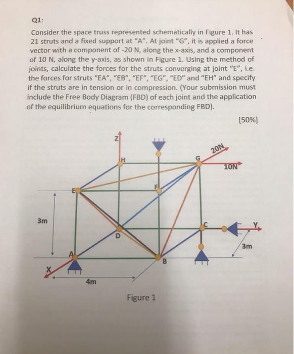
give answer in 2 step with explanation at the end of each step and final answer at the end:Qi: Consider the space truss represented schematically in Figure 1. It has 21 struts and a fixed support at “A”. At joint “G”, it is applied a force * vector with a component of -20 N, along the x-axis, and a component of 10 N, along the y-axis, as shown in Figure 1. Using the method of joints, calculate the forces for the struts converging at joint “E”, i.e. the forces for struts “EA”, “EB”, “EF”, “EG”, “ED” and “EH” and specify if the struts are in tension or in compression. (Your submission must include the Free Body Diagram (FBD) of each joint and the application of the equilibrium equations for the corresponding FBD). (50%) pd 3 am N\ wz | SON | / A x 3m i | a J

Question:

give answer in 2 step with explanation at the end of each step and final answer at the end:Uploaded ImageQi: Consider the space truss represented schematically in Figure 1. It has 21 struts and a fixed support at “A”. At joint “G”, it is applied a force * vector with a component of -20 N, along the x-axis, and a component of 10 N, along the y-axis, as shown in Figure 1. Using the method of joints, calculate the forces for the struts converging at joint “E”, i.e. the forces for struts “EA”, “EB”, “EF”, “EG”, “ED” and “EH” and specify if the struts are in tension or in compression. (Your submission must include the Free Body Diagram (FBD) of each joint and the application of the equilibrium equations for the corresponding FBD). (50%) pd 3 am N\ wz | SON | / A x 3m i | a J
This is AI generated Response.
Asked by: Rahul
Created at: 2025-12-12 14:39:35

Final Answer:

Rendered Raw Text
Did you like this answer?
Let's break down the solution into **two main steps** as you requested. --- ## **Step 1: Draw the Free Body Diagram (FBD) of Joint E** ### **Explanation:** We need to analyze the forces acting at joint **E**. The struts converging at joint E are: - EA - EB - EF - EG - ED - EH For each strut, we must represent its force as acting **away from the joint** (assuming tension; if negative, it's in compression). ### **Coordinates (for direction vectors)** From the diagram, we assign coordinates: - \( A = (, , ) \) - \( B = (4, , ) \) - \( C = (4, 3, ) \) - \( D = (, 3, ) \) - \( E = (, 3, 3) \) - \( F = (4, 3, 3) \) - \( G = (4, 3, 6) \) - \( H = (, 3, 6) \) **E is at (, 3, 3).** #### **Strut Direction Vectors (from E):** - **EA:** A(,,) → E(,3,3): vector = (-, -3, -3) = (, -3, -3) - **EB:** B(4,,) → E(,3,3): vector = (4-, -3, -3) = (4, -3, -3) - **EF:** F(4,3,3) → E(,3,3): vector = (4-, 3-3, 3-3) = (4, , ) - **EG:** G(4,3,6) → E(,3,3): vector = (4-, 3-3, 6-3) = (4, , 3) - **ED:** D(,3,) → E(,3,3): vector = (-, 3-3, -3) = (, , -3) - **EH:** H(,3,6) → E(,3,3): vector = (-, 3-3, 6-3) = (, , 3) --- ## **Step 2: Write Equilibrium Equations for Joint E** ### **Explanation:** Sum of forces at joint E must be zero in all directions (x, y, z): \[ \sum F_x = , \quad \sum F_y = , \quad \sum F_z = \] Each force in a strut can be written as: \[ \vec{F} = F \cdot \hat{u} \] Where \( \hat{u} \) is the unit vector along the strut. #### **Find Unit Vectors:** For each strut, calculate its length and unit vector: - **EA:** Length = \( \sqrt{^2 + 3^2 + 3^2} = \sqrt{18} = 4.24 \) - Unit vector: \( (, -3/4.24, -3/4.24) = (, -.707, -.707) \) - **EB:** Length = \( \sqrt{4^2 + 3^2 + 3^2} = \sqrt{34} = 5.83 \) - Unit vector: \( (4/5.83, -3/5.83, -3/5.83) = (.686, -.514, -.514) \) - **EF:** Length = 4, Unit vector: (1, , ) - **EG:** Length = \( \sqrt{4^2 + ^2 + 3^2} = 5 \), Unit vector: (.8, , .6) - **ED:** Length = 3, Unit vector: (, , -1) - **EH:** Length = 3, Unit vector: (, , 1) #### **Write Equilibrium Equations:** Let: - \( F_{EA}, F_{EB}, ... \) be the force magnitudes in each strut (positive = tension). Write equations (sum of all components in x, y, z must be zero): **X-direction:** \[ = F_{EB} \cdot .686 + F_{EF} \cdot 1 + F_{EG} \cdot .8 \] **Y-direction:** \[ = F_{EA} \cdot (-.707) + F_{EB} \cdot (-.514) \] **Z-direction:** \[ = F_{EA} \cdot (-.707) + F_{EB} \cdot (-.514) + F_{EG} \cdot .6 + F_{ED} \cdot (-1) + F_{EH} \cdot 1 \] (Notice: Since no external force is directly applied at E, all equations sum to zero.) --- ## **Final Answer Format** You now have: - The **FBD for joint E** (step 1) - The **equilibrium equations** relating the six unknown strut forces (step 2). **Next steps (not requested):** To fully solve, you would need additional equations from other joints or use a matrix method, since you have more unknowns than equations at this joint alone. --- ### **Final Summary** - **Step 1:** Drew the Free Body Diagram for joint E and listed the direction vectors for all converging struts. - **Step 2:** Wrote the force equilibrium equations at joint E using the unit vectors for each strut. **To determine the actual forces and their nature (tension/compression), solve these equations (and possibly others from adjacent joints).**

📢 Instructions:

  • Ask anything relatd to above question only.
  • For new Question goto :

Study Help, Fast Answers

VIPSolutions focuses on clear, step‑by‑step explanations so you can learn quickly. Whether you need an AI‑generated walkthrough or a short hint to get unstuck, each solution is organized for fast reading and easy review later.

Search similar questions, compare approaches, and bookmark the best answers for revision. Our goal is simple: quick, reliable study help that feels natural—not noisy.