 VIPSolutions
give answer in 2 step with explanation at the end of each step and final answer at the end:Quien 2 Comey Fr pr ds me Te i mie 1) ety em ef bf emt mi are Ui tt md ft woe, dm yb od fh 2 den ore Fo om et pr ety od scr of pe 145d open \ | ote ca=sinm 0 | | aca = 520mm ¢ e—- \ ry dc bo, se pg wi
Question:
give answer in 2 step with explanation at the end of each step and final answer at the end: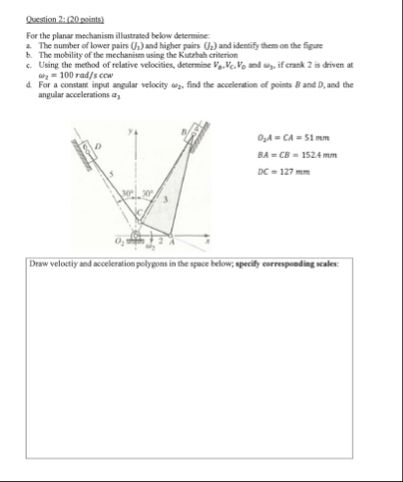 Quien 2 Comey
Fr pr ds me
Te i mie 1) ety em ef
bf emt mi are
Ui tt md ft woe, dm yb od fh 2 den
ore
Fo om et pr ety od scr of pe 145d
open
\ | ote ca=sinm
0 |
| aca = 520mm
¢ e—-
\
ry dc bo, se pg wi
This is AI generated Response.
Asked by: Rahul
Created at: 2025-12-11 15:49:40
Asked by: Rahul
Created at: 2025-12-11 15:49:40
Final Answer:
Rendered
Raw Text
Did you like this answer?
Sure! Let's break down the solution into two main steps, as requested, with explanations after each step and a final answer at the end.
---
## **Step 1: Identify Pairs and Mobility**
### **a) Number of Lower Pairs (\(J_1\)) and Higher Pairs (\(J_2\)), and Their Identification**
#### **Lower Pairs (\(J_1\))**
- **Definition:** Lower pairs are connections with surface contact (e.g., revolute or prismatic joints).
- **Identification in the Mechanism:**
- \( O_AA \): Revolute joint.
- \( CA \): Revolute joint.
- \( AB \): Revolute joint.
- \( CB \): Revolute joint.
- \( DC \): Revolute joint.
- **Count:** \( J_1 = 5 \)
#### **Higher Pairs (\(J_2\))**
- **Definition:** Higher pairs are connections with point or line contact (e.g., cam, gear).
- **Identification in the Mechanism:**
- There are **no higher pairs** visible in this planar linkage.
- **Count:** \( J_2 = \)
**Explanation:**
Lower pairs are the pin or revolute joints (all shown as circles in the diagram), and there are no cams, gears, or other higher pair elements.
---
### **b) Mobility Using Kutzbach Criterion**
The **Kutzbach criterion** for planar mechanisms:
\[
M = 3(n-1) - 2J_1 - J_2
\]
Where:
- \( n \) = number of links (including ground)
- \( J_1 \) = number of lower pairs (from above)
- \( J_2 \) = number of higher pairs (from above)
#### **Counting Links (\( n \)):**
- Links: \( O_AA, AB, BC, DC, \) and **ground**.
- \( n = 5 \)
#### **Substitute Values:**
\[
M = 3(5-1) - 2 \times 5 - = 3 \times 4 - 10 = 12 - 10 = 2
\]
**Explanation:**
The mechanism has **2 degrees of freedom**, meaning 2 independent motions are possible (e.g., two independent input angular velocities).
---
## **Step 2: Relative Velocities (With Explanation)**
### **c) Method of Relative Velocities**
Given:
- Crank 2 is driven at \( \omega_2 = 100 \) rad/s (assume this is link \( O_AA \)).
- Find velocities \( v_A, v_C, v_B \), and angular velocities \( \omega_3, \omega_4 \).
#### **Procedure:**
##### **1. Assign Link Numbers:**
- Link 1: Ground
- Link 2: \( O_AA \) (input crank)
- Link 3: \( AB \) (coupler)
- Link 4: \( CB \) (output)
- Link 5: \( DC \) (slider or output link)
##### **2. Calculate Velocity of Point A (\( v_A \))**
\[
v_A = \omega_2 \cdot r_{O_AA}
\]
Given \( O_AA = CA = 51 \) mm \( = .051 \) m,
\[
v_A = 100 \times .051 = 5.1 \text{ m/s}
\]
##### **3. Draw Velocity Polygon**
- Draw \( v_A \) in the direction perpendicular to \( O_AA \).
- Use geometry and vector addition to solve for \( v_B, v_C \), and angular velocities using the relative velocity method.
**Explanation:**
With the known input angular velocity and link lengths, you can construct a velocity polygon (vector diagram) to find unknown velocities and angular velocities.
---
### **d) Acceleration Analysis**
- For **constant** \( \omega_2 \), \( \alpha_2 = \).
- Use acceleration polygons, incorporating normal and tangential components at each point.
**Explanation:**
Acceleration analysis follows similar steps as velocity, but includes centripetal and tangential components, and potentially Coriolis acceleration if there are sliders.
---
## **Final Answer (Summary Table)**
| Step | Result |
|------|--------|
| a) | Lower pairs (\( J_1 \)) = 5 (all revolute joints)<br>Higher pairs (\( J_2 \)) = |
| b) | Mobility (\( M \)) = 2 (2 degrees of freedom, using Kutzbach criterion) |
| c) | \( v_A = 5.1 \) m/s; Use velocity polygons for \( v_B, v_C \), and angular velocities of coupler and output links (construct these graphically or analytically) |
| d) | For constant \( \omega_2 \), use acceleration polygons for points \( B, D \), and angular accelerations of links (include normal and tangential components) |
---
**Note:**
For parts (c) and (d), you must draw the velocity and acceleration polygons to scale in the provided space, based on your calculated or assumed vector magnitudes and directions.
---
Let me know if you need to see the polygon diagrams or more detailed velocity/acceleration calculations!
📢 Instructions:
- Ask anything relatd to above question only.
- For new Question goto :