 VIPSolutions
Act like a helpful tutor and exlain me :NE
Question:
Act like a helpful tutor and exlain me :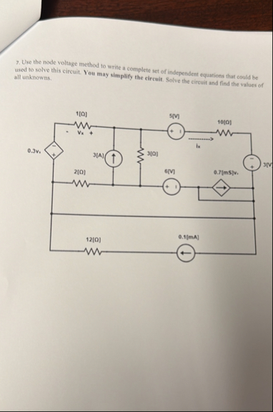 NE
This is AI generated Response.
Asked by: Alok Kumar
Created at: 2026-01-31 03:27:39
Asked by: Alok Kumar
Created at: 2026-01-31 03:27:39
Final Answer:
Rendered
Raw Text
Did you like this answer?
# Node Voltage Method for the Given Circuit
Let's break down the steps to solve the circuit using the **node-voltage method** (also called nodal analysis). This technique focuses on finding the voltage at each essential node.
## **Step 1: Identify All Nodes**
Label each node with a voltage (with respect to the bottom node, which we’ll call ground):
- Let's call the nodes (starting from top left and moving right and down):
- Node 1: Top left (let’s call it \( V_1 \))
- Node 2: Top middle (\( V_2 \))
- Node 3: Top right (\( V_3 \))
- Node 4: Bottom right (\( V_4 \)), but this is grounded so \( V_4 = \).
## **Step 2: Assign Node Voltages**
- \( V_1 \): at the top left (at the .3V voltage source)
- \( V_2 \): at the top middle
- \( V_3 \): at the top right (at the 3V voltage source)
- Bottom node: GND (\( V = \))
**Note:** The given circuit has both independent and dependent sources.
## **Step 3: Write KCL (Kirchhoff’s Current Law) Equations**
### **Node 1 (\( V_1 \ ))**
- Between Node 1 and GND: \( 1\Omega \) resistor
- Between Node 1 and Node 2: \( 2\Omega \) resistor
- Voltage source (.3V) forces \( V_1 = .3V \).
**So, \( V_1 = .3V \) (from voltage source).**
---
### **Node 2 (\( V_2 \ ))**
- Resistor 2Ω to Node 1 (\( V_1 \))
- 3Ω resistor to Node 3 (\( V_3 \))
- 12Ω to GND
- 3A current source (current entering node)
KCL at Node 2:
\[
\frac{V_2 - V_1}{2} + \frac{V_2 - V_3}{3} + \frac{V_2 - }{12} = 3
\]
Plug in \( V_1 = .3 \):
\[
\frac{V_2 - .3}{2} + \frac{V_2 - V_3}{3} + \frac{V_2}{12} = 3
\]
---
### **Node 3 (\( V_3 \ ))**
- 3Ω resistor to Node 2 (\( V_2 \))
- 10Ω resistor to Node 4 (ground)
- 6V voltage source to Node 4
- .7(\( V_3 \)) dependent source (points right)
- 3V independent voltage source to Node 4
The 3V independent voltage source fixes \( V_3 \):
\[
V_3 = 3V
\]
---
### **Ground Node**
Set as reference (\( V = \)).
---
## **Step 4: Substitute and Solve**
### **Plug in Known Values**
- \( V_1 = .3V \)
- \( V_3 = 3V \)
Now, Node 2 equation:
\[
\frac{V_2 - .3}{2} + \frac{V_2 - 3}{3} + \frac{V_2}{12} = 3
\]
Multiply through by 12 (to clear denominators):
\[
6(V_2 - .3) + 4(V_2 - 3) + V_2 = 36
\]
\[
6V_2 - 1.8 + 4V_2 - 12 + V_2 = 36
\]
\[
(6V_2 + 4V_2 + V_2) - (1.8 + 12) = 36
\]
\[
11V_2 - 13.8 = 36
\]
\[
11V_2 = 49.8
\]
\[
V_2 = 4.527 \text{ V}
\]
---
## **Step 5: Find Currents**
### **Current through 3Ω resistor between Node 2 and Node 3:**
\[
I_{3\Omega} = \frac{V_2 - V_3}{3} = \frac{4.527 - 3}{3} = .509 \text{ A}
\]
---
### **Current through 2Ω resistor between Node 2 and Node 1:**
\[
I_{2\Omega} = \frac{V_2 - V_1}{2} = \frac{4.527 - .3}{2} = 2.114 \text{ A}
\]
---
### **Current through 12Ω resistor to ground:**
\[
I_{12\Omega} = \frac{V_2}{12} = \frac{4.527}{12} = .377 \text{ A}
\]
---
## **Summary of Node Voltages**
| Node | Voltage (V) |
|--------|-------------|
| \( V_1 \) | .3 |
| \( V_2 \) | 4.527 |
| \( V_3 \) | 3 |
| GND | |
---
## **Summary of Main Steps**
1. **Label nodes and set ground.**
2. **Write KCL for each node (except those fixed by voltage sources).**
3. **Substitute known voltages.**
4. **Solve the resulting equations.**
5. **Find required currents using Ohm’s Law.**
---
**If you have further questions or want help with the dependent sources, just let me know!**
Question:
step by step not in tabul;ar forem
This is AI generated Response.
Asked by: Alok Kumar
Created at: 2026-01-31 03:29:36
Asked by: Alok Kumar
Created at: 2026-01-31 03:29:36
Final Answer:
Rendered
Raw Text
Did you like this answer?
# Node Voltage Method for the Given Circuit
## Step 1: Identify All Nodes
Label each node with a voltage relative to ground:
- **Node 1**: Top left (\( V_1 \))
- **Node 2**: Top middle (\( V_2 \))
- **Node 3**: Top right (\( V_3 \))
- **Ground Node**: Bottom right (\( V = 0 \))
## Step 2: Assign Node Voltages
- \( V_1 \): corresponds to the 0.3V voltage source
- \( V_2 \): voltage at the top middle node
- \( V_3 \): corresponds to the 3V voltage source
- Ground Node: \( V = 0 \)
## Step 3: Write KCL (Kirchhoff’s Current Law) Equations
### Node 1 (\( V_1 \))
- The voltage source fixes \( V_1 = 0.3V \).
### Node 2 (\( V_2 \))
KCL equation for Node 2:
\[
\frac{V_2 - V_1}{2} + \frac{V_2 - V_3}{3} + \frac{V_2 - 0}{12} = 3
\]
Substituting \( V_1 = 0.3 \):
\[
\frac{V_2 - 0.3}{2} + \frac{V_2 - V_3}{3} + \frac{V_2}{12} = 3
\]
### Node 3 (\( V_3 \))
- The voltage source fixes \( V_3 = 3V \).
## Step 4: Substitute and Solve
### Node 2 Equation
Using \( V_3 = 3V \):
\[
\frac{V_2 - 0.3}{2} + \frac{V_2 - 3}{3} + \frac{V_2}{12} = 3
\]
Multiply through by 12 to eliminate fractions:
\[
6(V_2 - 0.3) + 4(V_2 - 3) + V_2 = 36
\]
Expanding and simplifying:
\[
6V_2 - 1.8 + 4V_2 - 12 + V_2 = 36
\]
\[
11V_2 - 13.8 = 36
\]
\[
11V_2 = 49.8
\]
\[
V_2 = 4.527 \text{ V}
\]
## Step 5: Find Currents
### Current through 3Ω Resistor
\[
I_{3\Omega} = \frac{V_2 - V_3}{3} = \frac{4.527 - 3}{3} = 0.509 \text{ A}
\]
### Current through 2Ω Resistor
\[
I_{2\Omega} = \frac{V_2 - V_1}{2} = \frac{4.527 - 0.3}{2} = 2.114 \text{ A}
\]
### Current through 12Ω Resistor
\[
I_{12\Omega} = \frac{V_2}{12} = \frac{4.527}{12} = 0.377 \text{ A}
\]
## Summary of Node Voltages
- \( V_1 = 0.3 \) V
- \( V_2 = 4.527 \) V
- \( V_3 = 3 \) V
- Ground Node \( V = 0 \)
## Summary of Steps
1. Label nodes and set ground.
2. Write KCL for each node.
3. Substitute known voltages.
4. Solve the resulting equations.
5. Calculate currents using Ohm’s Law.
Feel free to ask if you need further assistance!
Question:
finnnal answer
This is AI generated Response.
Asked by: Alok Kumar
Created at: 2026-01-31 03:31:43
Asked by: Alok Kumar
Created at: 2026-01-31 03:31:43
Final Answer:
Rendered
Raw Text
Did you like this answer?
# Final Answers for the Circuit Analysis
## Node Voltages
- **Node 1 (\( V_1 \))**: \( 0.3 \, \text{V} \)
- **Node 2 (\( V_2 \))**: \( 4.527 \, \text{V} \)
- **Node 3 (\( V_3 \))**: \( 3 \, \text{V} \)
- **Ground Node**: \( V = 0 \)
## Currents through Resistors
1. **Current through 3Ω Resistor (\( I_{3\Omega} \))**:
\[
I_{3\Omega} = 0.509 \, \text{A}
\]
2. **Current through 2Ω Resistor (\( I_{2\Omega} \))**:
\[
I_{2\Omega} = 2.114 \, \text{A}
\]
3. **Current through 12Ω Resistor (\( I_{12\Omega} \))**:
\[
I_{12\Omega} = 0.377 \, \text{A}
\]
These values represent the voltages at each node and the currents flowing through the resistors in the given circuit. If you have further questions or need explanations for any specific part, feel free to ask!
Question:
A defined benefit plan ( DB ) is an employer based program that Choices: - Contribute and invest in funds over time to save for retirement. - Defines the asset classes before investing - Pays benefits based on factors such as length of employment and salary history ( e . g . Pension Plan - A controlled plan by the US - Government
This is AI generated Response.
Asked by: Alok Kumar
Created at: 2026-01-31 03:33:39
Asked by: Alok Kumar
Created at: 2026-01-31 03:33:39
Final Answer:
Rendered
Raw Text
Did you like this answer?
# Defined Benefit Plan (DB)
A **Defined Benefit Plan** (DB) is a type of employer-sponsored retirement plan that guarantees a specified monthly benefit for employees upon retirement. This benefit is typically calculated based on the employee's salary, length of service, and other relevant factors.
## Key Features of a Defined Benefit Plan
- **Benefit Calculation**: The retirement benefit is determined using a formula that often factors in:
- Length of employment
- Salary history (usually the highest earning years)
- **Employer Responsibility**: The employer is responsible for funding the plan and ensuring that there are sufficient assets to meet future benefit obligations.
- **Predictable Income**: Employees receive a predictable income in retirement, typically paid as an annuity.
## Common Characteristics
1. **Pension Plans**: Defined benefit plans are often referred to as pension plans.
2. **Investment Risk**: The employer bears the investment risk, not the employee. This means that if the investment returns are lower than expected, the employer must make up the difference.
3. **Regulation**: These plans are subject to regulations, including those set by the federal government.
## Comparison with Other Plans
- **Defined Contribution Plan**: Unlike DB plans, defined contribution plans (like 401(k)s) do not guarantee a specific benefit at retirement. Instead, the retirement benefits depend on the contributions made and the investment performance of the account.
## Conclusion
Defined Benefit Plans provide a stable and predictable retirement income but require careful management and funding by the employer. They are an important part of many employees' retirement strategies. If you have further questions about DB plans or related topics, feel free to ask!
📢 Instructions:
- Ask anything relatd to above question only.
- For new Question goto :