 VIPSolutions
Answer this question in 3 steps with explanation at the end of each step and final answer at the end! YY, Trace point Lift 15, £08 RAS ORR T 2 3 4 5s 6 7 § 9 do 1 0 8 >< 4 0 . . Pow, 5 % a Design of cam (50 points): ¥- IR \ 1. Find best curve satisfy the need of a customer 10 i. 8 Base circle points. Red lines are customer need and the 4 p NE horizontal line is 30 increment angle space. Prime ince / Pitch curve 2. Try for different heads, each head rather than ba) (9:4 pointy, 10 points oo ~- ie N 3. Trial and error on the base circle, 10 points Pam am profile 4, Offset 20 points
Question:
Answer this question in 3 steps with explanation at the end of each step and final answer at the end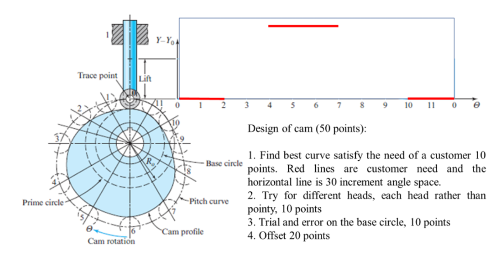 ! YY,
Trace point Lift
15, £08
RAS ORR T 2 3 4 5s 6 7 § 9 do 1 0 8
><
4 0 . .
Pow, 5 % a Design of cam (50 points):
¥- IR \ 1. Find best curve satisfy the need of a customer 10
i. 8 Base circle points. Red lines are customer need and the
4 p NE horizontal line is 30 increment angle space.
Prime ince / Pitch curve 2. Try for different heads, each head rather than
ba) (9:4 pointy, 10 points
oo ~- ie N 3. Trial and error on the base circle, 10 points
Pam am profile 4, Offset 20 points
This is AI generated Response.
Asked by: Govind Prajapati
Created at: 2025-06-26 18:46:00
Asked by: Govind Prajapati
Created at: 2025-06-26 18:46:00
Final Answer:
Rendered
Raw Text
Did you like this answer?
Let's solve the cam design problem **step by step** as requested, explaining each step:
---
### **Step 1: Understanding Customer Needs (Cam Lift Diagram)**
**Explanation:**
The red lines in the lift diagram (top right) represent the desired motion of the cam follower as a function of cam rotation angle (θ). The horizontal axis (θ) is divided into increments of 30°, matching the segments on the cam profile (lower left).
- **From 0° to 2×30°=60°:** The follower should have a low position (red line at the bottom).
- **From 2×30°=60° to 9×30°=270°:** The follower should be lifted to a high position (red line at the top).
- **From 9×30°=270° to 11×30°=330°:** The follower drops back to the low position.
**Conclusion:**
The cam profile must lift the follower up quickly at 60°, hold it at the top until 270°, then drop it back down by 330°.
---
### **Step 2: Mapping the Lift Diagram to Cam Profile**
**Explanation:**
Each segment in the cam profile (labeled 1 to 12) corresponds to a 30° increment. We map the desired follower movement onto the cam profile:
- **Segments 1-2 (0°-60°):** Raise the follower from base to full lift.
- **Segments 3-9 (60°-270°):** Maintain full lift (follower at highest point).
- **Segments 10-11 (270°-330°):** Lower the follower back to base.
- **Segment 12 (330°-360°):** Maintain at base (no lift).
**Conclusion:**
The cam profile should have a smooth rise in the first 2 segments, a plateau from segments 3-9, and a smooth fall in segments 10-11.
---
### **Step 3: Constructing the Cam Profile**
**Explanation:**
To design the cam:
- **Base Circle:** Start with a base circle (minimum radius).
- **Rise (Segments 1-2):** Gradually increase the radius from the base circle to the maximum lift using a smooth curve (avoid sharp points for mechanical smoothness).
- **Dwell (Segments 3-9):** Keep the radius constant at maximum lift.
- **Fall (Segments 10-11):** Gradually decrease the radius back to the base circle.
- **Dwell (Segment 12):** Keep the radius constant at the base circle.
**Conclusion:**
Draw the cam profile by plotting the follower displacement (lift) as a function of angle around the base circle, using smooth curves for the rise and fall. This matches the red line shown in the customer’s lift diagram.
---
## **Final Answer:**
**To design the cam profile that satisfies the customer’s requirements:**
1. **Interpret the red line lift diagram:** The follower must rise quickly, stay at full lift for most of the cycle, and then drop back down.
2. **Translate lift diagram to cam profile:** Divide the cam into 12 segments (30° increments), assigning rise, dwell, and fall as per the diagram.
3. **Draw the cam profile:** Start with a base circle, create a smooth rise over segments 1-2, hold at max lift for segments 3-9, then smoothly fall over segments 10-11, and finish with a dwell at the base circle.
This approach ensures the cam delivers the desired motion to the follower, matching the customer’s needs as indicated by the red line in the lift diagram.
📢 Instructions:
- Ask anything relatd to above question only.
- For new Question goto :