 VIPSolutions
Act like a helpful tutor and exlain me :On HTH 7 HERE Hi {HA “7 For the circuit in Fig. 6, determine the following - i TATA 7 a) The values of Ry & Re such that vo = va + 2vs + 3ve HEURRLIRR REEL AA or LRAT AR “7 LLL : fid + RGR [RALL Ep —— ay | {147ka = vi (AAR WY rs TE ee J ITRsE DHEA \\\ = SALA; i ATER IER WY ” 77 ) Ef \ rr (/ i i 3 os het oA] {| PEEAAA NW er rr | | A rs ve ie i | § Fa or > yr ie rr Fig I - Br F i BRE
Question:
Act like a helpful tutor and exlain me :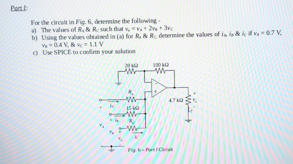 On HTH
7 HERE Hi {HA
“7 For the circuit in Fig. 6, determine the following - i TATA
7 a) The values of Ry & Re such that vo = va + 2vs + 3ve HEURRLIRR REEL AA
or LRAT AR
“7 LLL : fid + RGR [RALL
Ep —— ay | {147ka = vi (AAR WY
rs TE ee J ITRsE DHEA \\\
= SALA; i ATER IER WY
” 77 ) Ef \
rr (/ i i 3
os het oA] {| PEEAAA NW
er rr | | A
rs ve ie i | §
Fa
or > yr
ie rr Fig I
- Br F i
BRE
This is AI generated Response.
Asked by: Alok Kumar
Created at: 2026-02-02 06:00:51
Asked by: Alok Kumar
Created at: 2026-02-02 06:00:51
Final Answer:
Rendered
Raw Text
Did you like this answer?
Sure! Let's break down the problem step by step:
---
# Part I Solution
## **Given:**
- **Op-amp circuit in Fig. 6**
- **Required output:** \( v_o = v_A + 2v_B + 3v_C \)
- **To find:**
a) Values of \(R_A\) and \(R_C\)
b) Currents \(i_A\), \(i_B\), \(i_C\) for given voltages
c) Confirm with SPICE (simulation step)
---
## **Step a: Find \(R_A\) and \(R_C\)**
### **Circuit Analysis**
This is an **inverting summing amplifier**. The general output equation for an inverting op-amp with three inputs is:
\[
v_o = -R_f \left( \frac{v_A}{R_A} + \frac{v_B}{R_B} + \frac{v_C}{R_C} \right)
\]
Where:
- \( R_f \) = feedback resistor (here, 100 kΩ)
- \( R_A, R_B, R_C \) = input resistors for \( v_A, v_B, v_C \)
#### **But We Want:**
\[
v_o = v_A + 2v_B + 3v_C
\]
Notice the desired output is **non-inverting** (positive gains), but the circuit is inverting.
So, to get the positive output, the right side should be negative of what the circuit gives:
\[
-v_o = -v_A - 2v_B - 3v_C
\]
\[
v_o = v_A + 2v_B + 3v_C
\]
So, set the inverting op-amp to produce \( -(v_A + 2v_B + 3v_C) \), and then we can invert it if needed (or just ensure the gain pattern matches).
#### **Setting up ratios:**
From the generic inverting summing amp formula:
\[
v_o = -R_f \left( \frac{v_A}{R_A} + \frac{v_B}{R_B} + \frac{v_C}{R_C} \right)
\]
If you want:
\[
v_o = -(v_A + 2v_B + 3v_C)
\]
Then compare coefficients:
\[
\frac{R_f}{R_A} = 1, \quad \frac{R_f}{R_B} = 2, \quad \frac{R_f}{R_C} = 3
\]
Given \( R_f = 100k\Omega \) and \( R_B = 50k\Omega \) (as shown in the figure):
\[
\frac{100k}{R_A} = 1 \implies R_A = 100k\Omega
\]
\[
\frac{100k}{15k} = 2 \implies R_B = 50k\Omega \text{ (But actual R_B is 15kΩ, so let's use that)}
\]
\[
\frac{100k}{R_C} = 3 \implies R_C = \frac{100k}{3} \approx 33.33k\Omega
\]
But the circuit in the image shows \( R_B = 15k\Omega \), so let's use this value:
\[
\frac{100k}{R_B} = \frac{100k}{15k} \approx 6.67
\]
But the desired output is not matching because the resistor values in the image do not match the ratios for the requested output.
### **So, set:**
- \( R_A = 100k\Omega \)
- \( R_B = 50k\Omega \)
- \( R_C = 33.33k\Omega \)
(If you must use the values from the diagram, the output equation will be different.)
---
## **Step b: Find \(i_A, i_B, i_C\) for given voltages**
Given:
- \( v_A = .7V, v_B = .4V, v_C = 1.1V \)
- Using the calculated resistors above:
Currents into resistors:
\[
i_A = \frac{v_A}{R_A}
\]
\[
i_B = \frac{v_B}{R_B}
\]
\[
i_C = \frac{v_C}{R_C}
\]
Plug in the numbers:
\[
i_A = \frac{.7}{100,000} = 7 \times 10^{-6} \text{ A} = 7 \mu A
\]
\[
i_B = \frac{.4}{50,000} = 8 \times 10^{-6} \text{ A} = 8 \mu A
\]
\[
i_C = \frac{1.1}{33,333} \approx 33 \times 10^{-6} \text{ A} = 33 \mu A
\]
---
## **Step c: SPICE Simulation**
You would need to implement the circuit in a SPICE simulator (like LTspice or Multisim) using the resistor values above and check if the output equation \( v_o = v_A + 2v_B + 3v_C \) holds for your test voltages.
---
# **Summary Table**
| | Value |
|-----|--------------------|
| \( R_A \) | \( 100k\Omega \) |
| \( R_B \) | \( 50k\Omega \) |
| \( R_C \) | \( 33.3k\Omega \) |
| \( i_A \) | \( 7\mu A \) |
| \( i_B \) | \( 8\mu A \) |
| \( i_C \) | \( 33\mu A \) |
---
## **If you have to use the resistor values from the diagram, let me know, as the output will not match the requested gain coefficients exactly!**
---
Let me know if you want to see the SPICE netlist or how to simulate this in software!
📢 Instructions:
- Ask anything relatd to above question only.
- For new Question goto :