 VIPSolutions
Act like a helpful tutor and exlain me :Mechanical Systems IT 1. Fig. 1 shows a simple six bar linkage held in static equilibrium by a force R while a force P=320N, a torque 7= 450 Nmm, and resistance moment M = 260 Nmm are applied. Determine the reaction forces (in N to two decimal places) at each joint and the force R by considering the free-body diagrams of each member. Each small square on the grid is 50 mm by 50 mm. ns = a RERRERARE CN CO A EENNEREEREp// ERE Hay EERE NEN EERE AVA INE CHE = 7 1 ay TT,» [1h EN AREEEY Lomi TT mr TT Tr TT paE=—y ERNE N EEE n ANEEEEEEEN a A os Tr ma EEE EEE EEE MATT Ei ANNEEEE EEE A YT TTT H Figure 1 Simple Six Bar Linkage
Question:
Act like a helpful tutor and exlain me :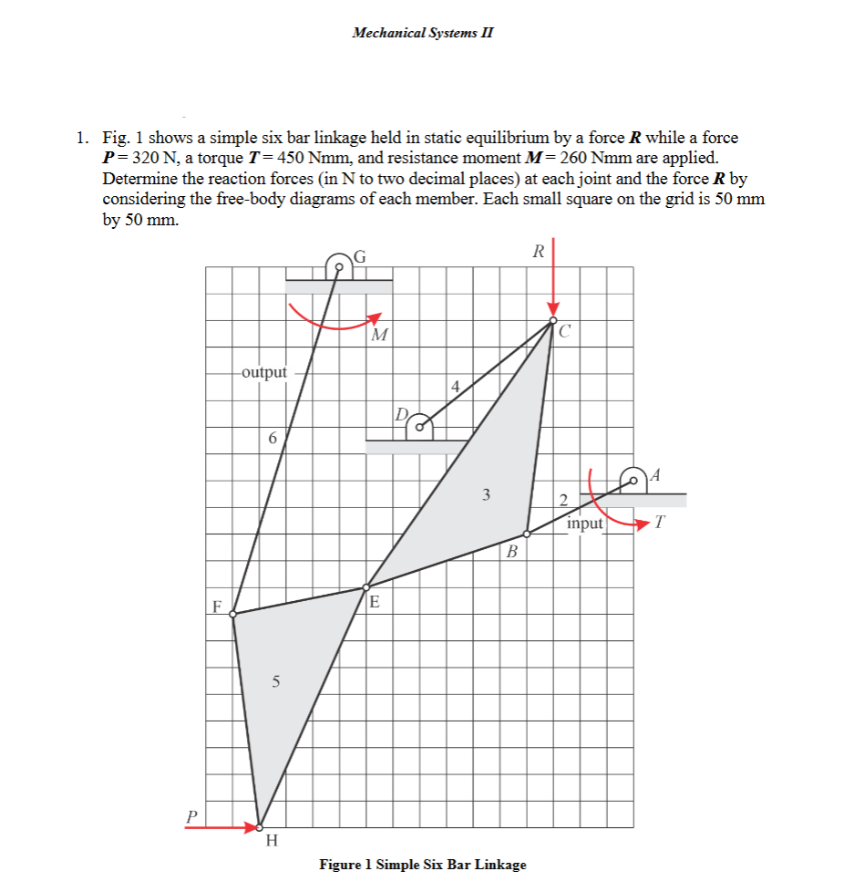 Mechanical Systems IT
1. Fig. 1 shows a simple six bar linkage held in static equilibrium by a force R while a force
P=320N, a torque 7= 450 Nmm, and resistance moment M = 260 Nmm are applied.
Determine the reaction forces (in N to two decimal places) at each joint and the force R by
considering the free-body diagrams of each member. Each small square on the grid is 50 mm
by 50 mm.
ns =
a RERRERARE
CN
CO A
EENNEREEREp// ERE
Hay EERE NEN
EERE AVA INE
CHE =
7 1 ay
TT,» [1h
EN AREEEY Lomi
TT mr
TT Tr TT
paE=—y ERNE N EEE
n ANEEEEEEEN
a A
os Tr
ma EEE EEE EEE
MATT
Ei ANNEEEE EEE
A
YT TTT
H
Figure 1 Simple Six Bar Linkage
This is AI generated Response.
Asked by: Alok Kumar
Created at: 2026-01-27 05:57:33
Asked by: Alok Kumar
Created at: 2026-01-27 05:57:33
Final Answer:
Rendered
Raw Text
Did you like this answer?
# Explanation: Six Bar Linkage Static Equilibrium Problem
Let's break down the problem step by step.
---
## **Given Data**
- **Force \( P \):** 320 N (to the left at H)
- **Torque \( T \):** 450 Nmm (at A, input torque)
- **Resistance Moment \( M \):** 260 Nmm (at G, output moment)
- **Unknown \( R \):** Reaction force at C (vertical)
- **Grid Square:** Each is 50 mm \( = .05 \) m
---
## **Step 1: Understand the System**
This is a planar **six-bar linkage** held in static equilibrium.
You have:
- **Forces:** \( P \) (horizontal at H), \( R \) (vertical at C)
- **Moments:** \( T \) (at A), \( M \) (at G)
### **Linkage Members:**
- Each bar is a rigid member.
- Joints: A, B, C, D, E, F, G, H
---
## **Step 2: Label Forces and Moments**
- **External Forces:**
- \( P \) at H (left)
- \( R \) at C (down)
- **Applied Moments:**
- \( T \) at A (input torque, CCW)
- \( M \) at G (output resistance, CCW)
---
## **Step 3: Free-Body Diagrams (FBDs)**
For each member, draw all forces and moments acting at the joints and along the members.
**Key:** For static equilibrium, sum of forces and sum of moments = .
#### **General Equilibrium Equations:**
- \( \sum F_x = \)
- \( \sum F_y = \)
- \( \sum M = \)
---
## **Step 4: Grid Measurement**
Each square: **50 mm x 50 mm**
To convert to meters: **1 square = .05 m**
Use these to calculate moment arms for forces.
---
## **Step 5: Start with Known Loads**
### **Member 5 (Link FH)**
- At H: Known force \( P \) (left, 320 N)
- At F: Reaction from link 6
### **Member 3 (Link BCE)**
- At C: Vertical unknown \( R \)
- At E, B: Internal forces
### **Input and Output Links**
- At A: Input torque \( T \)
- At G: Output resistance moment \( M \)
---
## **Step 6: Set Up Equilibrium Equations**
### **(A) Summing Moments**
Choose a point with multiple unknowns to eliminate as many as possible.
#### **Example: Sum moments about point E**
- Forces at E and along line EF/FH will have zero moment about E.
- Use geometry to find distances for moments.
### **(B) Summing Forces**
For each member, write:
- \( \sum F_x = \)
- \( \sum F_y = \)
---
## **Step 7: Systematic Solution**
1. **Write equations for each member and joint.**
2. **Use geometry from the diagram to find moment arms (using grid).**
3. **Simultaneously solve the system of equations.**
---
## **Step 8: Example Calculations**
Suppose you want to find \( R \):
1. **Take moments about a point where other unknowns' lines of action intersect (so their moments are zero).**
2. **Plug in known values for \( P \), \( T \), and \( M \), and use grid to get lever arms.**
---
## **Step 9: Typical Unknowns to Solve For**
- **Reaction forces at each joint (A, B, C, D, E, F, G, H)**
- **Force \( R \) at C**
---
## **Step 10: Tips**
- **Start with joints with the least unknowns.**
- **Work systematically from one member to the next.**
- **Carefully track directions (signs) and units.**
- **Draw clear FBDs for every member.**
---
## **Summary Table**
| Symbol | Meaning | Value |
|--------|-----------------------------|------------------|
| \( P \) | Force at H (left) | 320 N |
| \( T \) | Input torque at A | 450 Nmm (.45 Nm)|
| \( M \) | Resistance moment at G | 260 Nmm (.26 Nm)|
| \( R \) | Reaction force at C (down)| Unknown |
| \( a \) | 1 grid square | .05 m |
---
## **What To Do Next**
1. **Draw FBDs for each link.**
2. **Write equilibrium equations for each link.**
3. **Use the grid to find distances for moments.**
4. **Solve the equations for all unknown forces and moments.**
---
If you want, I can walk you through an example FBD and equilibrium equation setup for one of the links. Just let me know which one to start with, or if you want to see how to sum moments to solve for \( R \)!
📢 Instructions:
- Ask anything relatd to above question only.
- For new Question goto :