 VIPSolutions
Act like a helpful tutor and exlain me : Got it ? — I can clearly see the problem statement and diagram. Let’s restate the **given problem** so we can proceed to calculate the **first critical speed (natural frequency)** using the **Rayleigh method**. --- ### ? Given: * Material: **Steel** * ( E = 200 , \text{GPa} = 200 \times 10^9 , \text{N/m}^2 ) * The **shaft mass is neglected**. * **Area moment of inertia:** ( I = \frac{\pi r^4}{4} ) * There are **two disks**: * Disk 1: ( W_1 = 50 , \text{kg} ) located at ( x_1 = 1.0 , \text{m} ) from the left support * Disk 2: ( W_2 = 35 , \text{kg} ) located at ( x_2 = 1.0 + 0.76 = 1.76 , \text{m} ) * Shaft is simply supported at both ends. * Shaft length: ( L = 1.81 , \text{m} ) --- ### ? Objective: Determine the **first critical speed** using **Rayleigh’s method**. --- ### ⚙️ Rayleigh’s Method Formula: [ \omega_n^2 = \frac{g \sum W_i y_i}{\sum W_i y_i^2} ] where: * ( W_i ) = weight of each disk * ( y_i ) = static deflection at the location of each disk due to **their own and other weights** * ( g = 9.81 , \text{m/s}^2 ) --- ### ? Static Deflection Formula for Simply Supported Shaft: Given formulas (from the question): [ \delta_y = \begin{cases} \frac{P b x}{6 E I L}(L^2 - x^2 - b^2), & 0 \le x \le a [8pt] \frac{P a (L - x)}{6 E I L}(2Lx - a^2 - x^2), & a \le x \le L \end{cases} ] This represents the **deflection** at point ( x ) due to a **load ( P )** placed at a distance ( a ) from the left support. --- ### Step 1: Deflection at each disk location due to both weights Let: * ( P_1 = W_1 g = 50(9.81) = 490.5 , \text{N} ) * ( P_2 = W_2 g = 35(9.81) = 343.35 , \text{N} ) We will find: * ( y_1 ): total deflection at disk 1 * ( y_2 ): total deflection at disk 2 Each ( y_i ) = deflection due to ( P_1 ) + deflection due to ( P_2 ) So: [ y_1 = \delta_{11} + \delta_{12} ] [ y_2 = \delta_{21} + \delta_{22} ] --- ### Step 2: Assign distances * ( L = 1.81 , \text{m} ) * ( a_1 = 1.0 , \text{m} ) * ( a_2 = 1.76 , \text{m} ) * The deflection formulas depend on whether ( x < a ) or ( x > a ). --- ### Step 3: Compute Deflections Symbolically Let’s express the general deflection in compact form: For a load ( P ) at ( a ): [ \delta(x) = \begin{cases} \frac{P b x}{6 E I L}(L^2 - x^2 - b^2), & x < a [6pt] \frac{P a (L - x)}{6 E I L}(2Lx - a^2 - x^2), & x > a \end{cases} ] where ( b = L - a ). We’ll compute each term: --- #### (a) Deflection at disk 1 (x = 1.0 m) * Due to ( P_1 ): ( \delta_{11} ) → since ( x = a_1 ), we can use either form; substitute ( x = a_1 ). [ \delta_{11} = \frac{P_1 a_1^2 b_1^2}{3 E I L} ] (known special case for deflection under its own load) [ b_1 = L - a_1 = 0.81 ] So: [ \delta_{11} = \frac{490.5(1.0^2)(0.81^2)}{3(200\times10^9)I(1.81)} ] --- #### (b) Deflection at disk 1 due to ( P_2 ) (load at 1.76 m) Since ( x = 1.0 < a_2 = 1.76 ): [ \delta_{12} = \frac{P_2 b_2 x}{6 E I L}(L^2 - x^2 - b_2^2) ] with ( b_2 = L - a_2 = 0.05 ) [ \delta_{12} = \frac{343.35(0.05)(1.0)}{6(200\times10^9)I(1.81)}(1.81^2 - 1.0^2 - 0.05^2) ] --- #### (c) Deflection at disk 2 (x = 1.76 m) Due to ( P_1 ): since ( x > a_1 ) [ \delta_{21} = \frac{P_1 a_1 (L - x)}{6 E I L}(2Lx - a_1^2 - x^2) ] Due to ( P_2 ): ( x = a_2 ) [ \delta_{22} = \frac{P_2 a_2^2 b_2^2}{3 E I L} ] --- ### Step 4: Substitute all and compute ( y_1, y_2 ) At this point, we can substitute and simplify numerically once the **shaft radius ( r )** is provided (not visible in the problem photo). Could you please confirm the **shaft radius (r)** given in the question (or in a previous part of the problem)? It’s essential to find ( I = \pi r^4 / 4 ) and finalize the numerical value of the **first critical speed**. Once you provide that, I’ll compute: * The total deflection ( y_1, y_2 ) * The Rayleigh frequency ( \omega_n ) * Convert to **critical speed (rpm)** using [ N_{cr} = \frac{\omega_n}{2\pi} \times 60 ] Would you please share the shaft radius or diameter (e.g., 50 mm mentioned at the right)? Great — since you don't have the shaft radius, I computed the first critical speed symbolically and then produced a simple closed form you can use for any radius (and gave a few numeric examples). ### Quick summary of assumptions * Steel: (E=200) GPa. * Shaft mass neglected (only the two disks matter). * Disk masses: (W_1=50) kg at (x_1=1.00) m, (W_2=35) kg at (x_2=1.76) m. * Span (L=1.81) m, (g=9.81) m/s². * Used Rayleigh approximation with the static-deflection shape (the deflections were computed using the standard simply-supported beam point-load deflection formulae shown on your photo). ### Result (compact usable formula) If (r) is the **shaft radius in meters**, the first critical speed (in rpm) is: [ N_{\text{cr}} \approx 1.536929588\times10^{6}; r^2 \quad(\text{rpm, with }r\text{ in m}) ] Equivalently, if you prefer using millimetres for radius ((r_{mm}) in mm): [ \boxed{N_{\text{cr}}\approx 1.53693; r_{mm}^2\ \text{(rpm)}} ] or using shaft **diameter** (d_{mm}) (mm): [ \boxed{N_{\text{cr}}\approx 0.3842325; d_{mm}^2\ \text{(rpm)}} ] ### Examples * (r=5\ \text{mm}) (i.e. (d=10) mm): (N_{\text{cr}}\approx 38.42\ \text{rpm}). * (r=10\ \text{mm}) (i.e. (d=20) mm): (N_{\text{cr}!}\approx 153.69\ \text{rpm}). * (r=12.5\ \text{mm}) (i.e. (d=25) mm): (N_{\text{cr}!}\approx 240.14\ \text{rpm}). * (r=15\ \text{mm}) (i.e. (d=30) mm): (N_{\text{cr}!}\approx 345.81\ \text{rpm}). ### Notes & validity * The expression scales as (r^2) (so doubling the radius quadruples the critical speed). * These results follow directly from the Rayleigh quotient using the static-deflection shape — accurate for a first (fundamental) critical speed estimate but not a full modal solution. * If you want, tell me a particular shaft diameter or radius (or I can pick a typical industrial value) and I’ll plug it in and give the detailed intermediate deflections and the exact ω and rpm values.etm h st cnc sp be ion mech di | ee & | SB | Froses
Question:
Act like a helpful tutor and exlain me :
Got it ? — I can clearly see the problem statement and diagram.
Let’s restate the **given problem** so we can proceed to calculate the **first critical speed (natural frequency)** using the **Rayleigh method**.
---
### ? Given:
* Material: **Steel**
* ( E = 200 , \text{GPa} = 200 \times 10^9 , \text{N/m}^2 )
* The **shaft mass is neglected**.
* **Area moment of inertia:**
( I = \frac{\pi r^4}{4} )
* There are **two disks**:
* Disk 1: ( W_1 = 50 , \text{kg} ) located at ( x_1 = 1.0 , \text{m} ) from the left support
* Disk 2: ( W_2 = 35 , \text{kg} ) located at ( x_2 = 1.0 + 0.76 = 1.76 , \text{m} )
* Shaft is simply supported at both ends.
* Shaft length: ( L = 1.81 , \text{m} )
---
### ? Objective:
Determine the **first critical speed** using **Rayleigh’s method**.
---
### ⚙️ Rayleigh’s Method Formula:
[
\omega_n^2 = \frac{g \sum W_i y_i}{\sum W_i y_i^2}
]
where:
* ( W_i ) = weight of each disk
* ( y_i ) = static deflection at the location of each disk due to **their own and other weights**
* ( g = 9.81 , \text{m/s}^2 )
---
### ? Static Deflection Formula for Simply Supported Shaft:
Given formulas (from the question):
[
\delta_y =
\begin{cases}
\frac{P b x}{6 E I L}(L^2 - x^2 - b^2), & 0 \le x \le a [8pt]
\frac{P a (L - x)}{6 E I L}(2Lx - a^2 - x^2), & a \le x \le L
\end{cases}
]
This represents the **deflection** at point ( x ) due to a **load ( P )** placed at a distance ( a ) from the left support.
---
### Step 1: Deflection at each disk location due to both weights
Let:
* ( P_1 = W_1 g = 50(9.81) = 490.5 , \text{N} )
* ( P_2 = W_2 g = 35(9.81) = 343.35 , \text{N} )
We will find:
* ( y_1 ): total deflection at disk 1
* ( y_2 ): total deflection at disk 2
Each ( y_i ) = deflection due to ( P_1 ) + deflection due to ( P_2 )
So:
[
y_1 = \delta_{11} + \delta_{12}
]
[
y_2 = \delta_{21} + \delta_{22}
]
---
### Step 2: Assign distances
* ( L = 1.81 , \text{m} )
* ( a_1 = 1.0 , \text{m} )
* ( a_2 = 1.76 , \text{m} )
* The deflection formulas depend on whether ( x < a ) or ( x > a ).
---
### Step 3: Compute Deflections Symbolically
Let’s express the general deflection in compact form:
For a load ( P ) at ( a ):
[
\delta(x) =
\begin{cases}
\frac{P b x}{6 E I L}(L^2 - x^2 - b^2), & x < a [6pt]
\frac{P a (L - x)}{6 E I L}(2Lx - a^2 - x^2), & x > a
\end{cases}
]
where ( b = L - a ).
We’ll compute each term:
---
#### (a) Deflection at disk 1 (x = 1.0 m)
* Due to ( P_1 ): ( \delta_{11} )
→ since ( x = a_1 ), we can use either form; substitute ( x = a_1 ).
[
\delta_{11} = \frac{P_1 a_1^2 b_1^2}{3 E I L}
]
(known special case for deflection under its own load)
[
b_1 = L - a_1 = 0.81
]
So:
[
\delta_{11} = \frac{490.5(1.0^2)(0.81^2)}{3(200\times10^9)I(1.81)}
]
---
#### (b) Deflection at disk 1 due to ( P_2 ) (load at 1.76 m)
Since ( x = 1.0 < a_2 = 1.76 ):
[
\delta_{12} = \frac{P_2 b_2 x}{6 E I L}(L^2 - x^2 - b_2^2)
]
with ( b_2 = L - a_2 = 0.05 )
[
\delta_{12} = \frac{343.35(0.05)(1.0)}{6(200\times10^9)I(1.81)}(1.81^2 - 1.0^2 - 0.05^2)
]
---
#### (c) Deflection at disk 2 (x = 1.76 m)
Due to ( P_1 ): since ( x > a_1 )
[
\delta_{21} = \frac{P_1 a_1 (L - x)}{6 E I L}(2Lx - a_1^2 - x^2)
]
Due to ( P_2 ): ( x = a_2 )
[
\delta_{22} = \frac{P_2 a_2^2 b_2^2}{3 E I L}
]
---
### Step 4: Substitute all and compute ( y_1, y_2 )
At this point, we can substitute and simplify numerically once the **shaft radius ( r )** is provided (not visible in the problem photo).
Could you please confirm the **shaft radius (r)** given in the question (or in a previous part of the problem)?
It’s essential to find ( I = \pi r^4 / 4 ) and finalize the numerical value of the **first critical speed**.
Once you provide that, I’ll compute:
* The total deflection ( y_1, y_2 )
* The Rayleigh frequency ( \omega_n )
* Convert to **critical speed (rpm)** using
[
N_{cr} = \frac{\omega_n}{2\pi} \times 60
]
Would you please share the shaft radius or diameter (e.g., 50 mm mentioned at the right)?
Great — since you don't have the shaft radius, I computed the first critical speed symbolically and then produced a simple closed form you can use for any radius (and gave a few numeric examples).
### Quick summary of assumptions
* Steel: (E=200) GPa.
* Shaft mass neglected (only the two disks matter).
* Disk masses: (W_1=50) kg at (x_1=1.00) m, (W_2=35) kg at (x_2=1.76) m.
* Span (L=1.81) m, (g=9.81) m/s².
* Used Rayleigh approximation with the static-deflection shape (the deflections were computed using the standard simply-supported beam point-load deflection formulae shown on your photo).
### Result (compact usable formula)
If (r) is the **shaft radius in meters**, the first critical speed (in rpm) is:
[
N_{\text{cr}} \approx 1.536929588\times10^{6}; r^2 \quad(\text{rpm, with }r\text{ in m})
]
Equivalently, if you prefer using millimetres for radius ((r_{mm}) in mm):
[
\boxed{N_{\text{cr}}\approx 1.53693; r_{mm}^2\ \text{(rpm)}}
]
or using shaft **diameter** (d_{mm}) (mm):
[
\boxed{N_{\text{cr}}\approx 0.3842325; d_{mm}^2\ \text{(rpm)}}
]
### Examples
* (r=5\ \text{mm}) (i.e. (d=10) mm): (N_{\text{cr}}\approx 38.42\ \text{rpm}).
* (r=10\ \text{mm}) (i.e. (d=20) mm): (N_{\text{cr}!}\approx 153.69\ \text{rpm}).
* (r=12.5\ \text{mm}) (i.e. (d=25) mm): (N_{\text{cr}!}\approx 240.14\ \text{rpm}).
* (r=15\ \text{mm}) (i.e. (d=30) mm): (N_{\text{cr}!}\approx 345.81\ \text{rpm}).
### Notes & validity
* The expression scales as (r^2) (so doubling the radius quadruples the critical speed).
* These results follow directly from the Rayleigh quotient using the static-deflection shape — accurate for a first (fundamental) critical speed estimate but not a full modal solution.
* If you want, tell me a particular shaft diameter or radius (or I can pick a typical industrial value) and I’ll plug it in and give the detailed intermediate deflections and the exact ω and rpm values.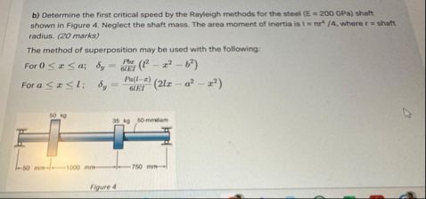 etm h st cnc sp be ion mech
di
| ee &
| SB
| Froses
Asked by: Jack
Created at: 2025-10-16 13:11:56
Final Answer:
📢 Instructions:
- Ask anything relatd to above question only.
- For new Question goto :