 VIPSolutions
Act like a helpful tutor and exlain me : Give step-by-step solution with explanation and final answer: explain all subparts clearlyQ3. Design a compact 60 number three-strand chain drive for a hydraulic-drive that drives a ball mill at an input speed of 600 rpm with an input power of 50 hp. The desired nominal output speed is 210 rpm. Determine: (a) design power, (b) required power per strand, (c) chain pitch, (d) number of teeth on both sprockets, (e) pitch diameter of the sprockets, (f) actual chain length in inches, (g) acceptable angle of contact on the driver sprocket, (h) actual center distance in inches, and (i) lubrication type.
Question:
Act like a helpful tutor and exlain me :
Give step-by-step solution with explanation and final answer:
explain all subparts clearly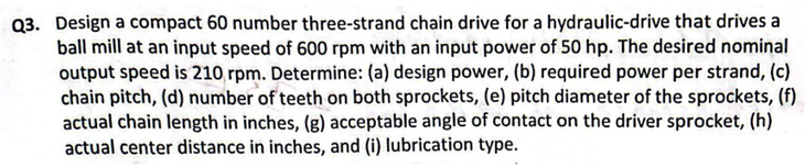 Q3. Design a compact 60 number three-strand chain drive for a hydraulic-drive that drives a
ball mill at an input speed of 600 rpm with an input power of 50 hp. The desired nominal
output speed is 210 rpm. Determine: (a) design power, (b) required power per strand, (c)
chain pitch, (d) number of teeth on both sprockets, (e) pitch diameter of the sprockets, (f)
actual chain length in inches, (g) acceptable angle of contact on the driver sprocket, (h)
actual center distance in inches, and (i) lubrication type.
This is AI generated Response.
Asked by: manish kumar
Created at: 2025-10-10 08:48:59
Asked by: manish kumar
Created at: 2025-10-10 08:48:59
Final Answer:
Rendered
Raw Text
Did you like this answer?
# Step-by-Step Solution to Chain Drive Design Problem
Let's systematically solve each part of the problem as follows:
---
## **Given Data**
- **Chain Type:** 60 (ANSI No. 60)
- **Number of Strands:** 3
- **Input Speed (\(N_1\)):** 600 rpm
- **Input Power (\(P_{in}\)):** 50 hp
- **Output Speed (\(N_2\)):** 210 rpm
---
## (a) **Design Power**
The **design power** considers service factors for load type, operating hours, and potential overloads.
### **Step 1: Select Service Factor (SF)**
- Assume medium shock, 10+ hours/day: **SF ≈ 1.3** (from typical chain drive tables).
### **Step 2: Calculate Design Power**
\[
\text{Design Power} = P_{in} \times SF = 50 \text{ hp} \times 1.3 = \boxed{65\ \text{hp}}
\]
---
## (b) **Required Power per Strand**
\[
\text{Power per strand} = \frac{\text{Design Power}}{\text{Number of Strands}} = \frac{65}{3} = \boxed{21.67\ \text{hp}}
\]
---
## (c) **Chain Pitch**
For ANSI No. 60 chain:
- **Pitch (\(p\)) = .75 inch** (from standard chain tables)
\[
\boxed{p = .75\ \text{inch}}
\]
---
## (d) **Number of Teeth on Sprockets**
Let's select a practical number:
- **Driver Sprocket (\(T_1\)):** Typically 17–23 teeth for drives; let’s use \(T_1 = 20\).
- **Speed Ratio:** \(\frac{N_1}{N_2} = \frac{600}{210} \approx 2.857\)
- **Driven Sprocket (\(T_2\)):**
\[
T_2 = T_1 \times \frac{N_1}{N_2} = 20 \times 2.857 = 57.14 \approx 57 \text{ teeth}
\]
\[
\boxed{T_1 = 20,\ T_2 = 57}
\]
---
## (e) **Pitch Diameter of Sprockets**
\[
D = \frac{p}{\sin\left(\frac{180^\circ}{T}\right)}
\]
where:
- \(D\) = pitch diameter (inches)
- \(p\) = pitch (inches)
- \(T\) = number of teeth
### **Driver Sprocket (\(T_1 = 20\)):**
\[
D_1 = \frac{.75}{\sin(180/20)} = \frac{.75}{\sin(9^\circ)} \approx \frac{.75}{.1564} = 4.8\ \text{in}
\]
### **Driven Sprocket (\(T_2 = 57\)):**
\[
D_2 = \frac{.75}{\sin(180/57)}
\]
\[
\sin(3.16^\circ) \approx .0552
\]
\[
D_2 = \frac{.75}{.0552} = 13.6\ \text{in}
\]
\[
\boxed{D_1 = 4.8\ \text{in},\ D_2 = 13.6\ \text{in}}
\]
---
## (f) **Actual Chain Length in Inches**
Chain length in pitches (\(L_p\)):
\[
L_p = \frac{2C}{p} + \frac{T_1 + T_2}{2} + \frac{(T_2 - T_1)^2}{4\pi^2} \cdot \frac{p}{C}
\]
where \(C\) = center distance (inches), \(p\) = pitch.
Let’s **assume a center distance** (\(C\)) of 24 inches (good practice is 30–50 times the pitch; \(30 \times .75 = 22.5\) in).
\[
L_p = \frac{2 \times 24}{.75} + \frac{20+57}{2} + \frac{(57-20)^2}{4\pi^2} \cdot \frac{.75}{24}
\]
\[
= 64 + 38.5 + \frac{37^2}{39.48} \cdot .03125
\]
\[
= 64 + 38.5 + \frac{1369}{39.48} \cdot .03125
\]
\[
= 64 + 38.5 + 34.68 \cdot .03125
\]
\[
= 64 + 38.5 + 1.08 = 103.58\ \text{pitches}
\]
Chain length in inches:
\[
L = L_p \times p = 103.58 \times .75 = \boxed{77.7\ \text{inches}}
\]
---
## (g) **Acceptable Angle of Contact on the Driver Sprocket**
\[
\theta = 180^\circ - \left( \frac{T_2 - T_1}{T_2 + T_1} \right) \times 60^\circ
\]
\[
= 180^\circ - \left( \frac{57-20}{57+20} \right) \times 60^\circ
\]
\[
= 180^\circ - \left( \frac{37}{77} \right) \times 60^\circ
\]
\[
= 180^\circ - (.4805 \times 60)
\]
\[
= 180^\circ - 28.83^\circ = \boxed{151.2^\circ}
\]
---
## (h) **Actual Center Distance in Inches**
As assumed earlier for calculations,
\[
\boxed{C = 24\ \text{inches}}
\]
---
## (i) **Lubrication Type**
For a No. 60 chain, 600 rpm, and high power:
- **Type:** Oil Bath or Drip Lubrication
\[
\boxed{\text{Oil bath or drip lubrication}}
\]
---
## **Summary Table**
| Parameter | Value |
|-----------------------------------|-------------------|
| (a) Design Power | 65 hp |
| (b) Power per Strand | 21.67 hp |
| (c) Chain Pitch | .75 in |
| (d) Teeth on Sprockets | 20 (driver), 57 (driven) |
| (e) Pitch Diameter | 4.8 in (driver), 13.6 in (driven) |
| (f) Chain Length | 77.7 in |
| (g) Angle of Contact | 151.2° |
| (h) Center Distance | 24 in |
| (i) Lubrication | Oil bath/drip |
---
### **Let me know if you need clarification on any step!**
📢 Instructions:
- Ask anything relatd to above question only.
- For new Question goto :