 VIPSolutions
Act like a helpful tutor and exlain me : Give step-by-step solution with explanation and final answer:A transmission system comprises a bevel gear derive arrangement as ‘shown in fig. 2.2. The bevel gear at B is positioned at mid-span of the shaft ABC of 1.2m long and transmits 15kW at 600rpm. The shaft is supported by bearings at A and C and which are assumed to be simply supported. The radial and axial components of the transmitted gear forces acting on the bevel gear are 1000N and 650N respectively as indicated. The yield strength for the shaft material is 310MN/n?’. Design the shaft by considering the factor of safety as 3. . 1000 N 650 N Bearing Bearing 2 \ == — EEE a AN dsl | ~~ NS IN Bevel gears i
Question:
Act like a helpful tutor and exlain me :
Give step-by-step solution with explanation and final answer: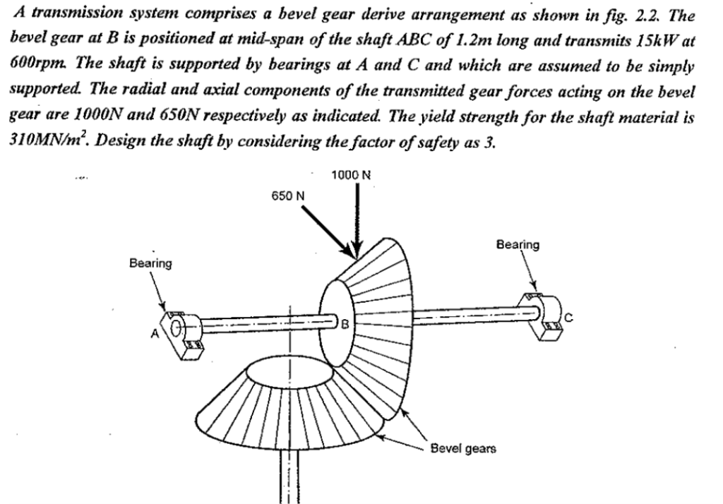 A transmission system comprises a bevel gear derive arrangement as ‘shown in fig. 2.2. The
bevel gear at B is positioned at mid-span of the shaft ABC of 1.2m long and transmits 15kW at
600rpm. The shaft is supported by bearings at A and C and which are assumed to be simply
supported. The radial and axial components of the transmitted gear forces acting on the bevel
gear are 1000N and 650N respectively as indicated. The yield strength for the shaft material is
310MN/n?’. Design the shaft by considering the factor of safety as 3.
. 1000 N
650 N
Bearing
Bearing 2 \
== — EEE a
AN dsl | ~~
NS
IN Bevel gears
i
This is AI generated Response.
Asked by: manish kumar
Created at: 2025-10-02 22:35:11
Asked by: manish kumar
Created at: 2025-10-02 22:35:11
Final Answer:
Rendered
Raw Text
Did you like this answer?
Let's break down the problem step by step:
---
## **Given Data**
- **Shaft Length (ABC)** 1.2 m
- **Power Transmitted (P = 15 kW = 15,000 W
- **Rotational Speed (N)** = 600 rpm
- **Radial Force B (F_r)** = 100 N
- **Axial Force at B (F_a)** = 650 N
- **Yield Strength (\(\sigma_{y}\))** = 310 MN/m² = \(310 \times 10^6\) N/m²
- **Factor of Safety (FOS)** = 3
---
## **Step 1: Calculate the Torque Transmitted**
\[
P = 2\pi N T / 60
\]
\[
T = \frac{P \times 60}{2\pi N}
\]
\[
T = \frac{15000 \times 60}{2\pi \times 600}
\]
\[
T = \frac{900000}{3769.9}
\]
\[
T = 238.7 \text{ Nm} = 238,700 \text{ Nmm}
\]
---
## **Step 2: Find Maximum Bending Moment (M)**
Since the gear is at the midpoint (B), reactions at A and C are equal and each force acts as a point load at midspan.
### **Vertical Plane (Radial Force, 100 N)**
- Each bearing reaction (vertical) = \(100/2 = 500\) N
- Maximum bending moment at B (center):
\[
M_{max,V} = 500 \text{ N} \times .6 \text{ m} = 300 \text{ Nm} = 300,000 \text{ Nmm}
\]
### **Horizontal Plane (Axial Force, 650 N)**
- Each bearing reaction (horizontal) = \(650/2 = 325\) N
- Maximum bending moment at B (center):
\[
M_{max,H} = 325 \text{ N} \times .6 \text{ m} = 195 \text{ Nm} = 195,000 \text{ Nmm}
\]
### **Resultant Maximum Bending Moment at B:**
\[
M_{max} = \sqrt{M_{max,V}^2 + M_{max,H}^2}
\]
\[
M_{max} = \sqrt{(300,000)^2 + (195,000)^2}
\]
\[
M_{max} = \sqrt{90 \times 10^{9} + 38.025 \times 10^{9}}
\]
\[
M_{max} = \sqrt{128.025 \times 10^{9}}
\]
\[
M_{max} \approx 357,850 \text{ Nmm}
\]
---
## **Step 3: Equivalent Twisting Moment (Combined Bending + Torsion)**
\[
T_{eq} = \sqrt{M_{max}^2 + T^2}
\]
\[
T_{eq} = \sqrt{(357,850)^2 + (238,700)^2}
\]
\[
= \sqrt{128.05 \times 10^9 + 57.02 \times 10^9}
\]
\[
= \sqrt{185.07 \times 10^9}
\]
\[
= 430,117 \text{ Nmm}
\]
---
## **Step 4: Allowable Stress**
\[
\text{Allowable Stress} = \frac{\sigma_{y}}{\text{FOS}} = \frac{310 \times 10^6}{3} = 103.33 \times 10^6 \text{ N/m}^2 = 103.33 \text{ N/mm}^2
\]
---
## **Step 5: Shaft Diameter Calculation**
For a solid shaft:
\[
\tau_{max} = \frac{16 T_{eq}}{\pi d^3}
\]
\[
d^3 = \frac{16 T_{eq}}{\pi \tau_{allowable}}
\]
\[
d^3 = \frac{16 \times 430,117}{\pi \times 103.33}
\]
\[
d^3 = \frac{6,481,872}{324.61}
\]
\[
d^3 = 19,972.6
\]
\[
d = \sqrt[3]{19,972.6}
\]
\[
d \approx 27.2 \text{ mm}
\]
---
## **Step 6: Final Shaft Diameter (with rounding)**
Always round **up** to the next standard shaft size for safety.
So, **shaft diameter = 28 mm (Standard Size)**.
---
# **Final Answer**
### **The recommended shaft diameter is:**
\[
\boxed{28\ \text{mm}}
\]
---
### **Summary of Steps:**
1. **Calculated Torque** from power and speed.
2. **Calculated Reactions and Max Bending Moments** (vertical & horizontal).
3. **Found Resultant Bending Moment** at gear location.
4. **Got Equivalent Twisting Moment** combining bending and torsion.
5. **Checked Allowable Shear Stress** using yield and FOS.
6. **Solved for Minimum Shaft Diameter** and rounded up.
---
**If you want to see calculations for a hollow shaft or further explanation on any step, let me know!**
📢 Instructions:
- Ask anything relatd to above question only.
- For new Question goto :