 VIPSolutions
Act like a helpful tutor and exlain me :A beam with the cross section shown is acted on by a bending moment of 10,000 Ib.in Determine (a) the maximum tensile and compressive bending stress and (b) the bending stress 1 inch from the bottom of the section. (draw stress distribution diagram with units ksi) di = 0.25 in. eh 0.25 in. i! 3in. 0.25 in. 4 ni J i
Question:
Act like a helpful tutor and exlain me :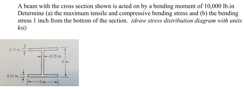 A beam with the cross section shown is acted on by a bending moment of 10,000 Ib.in
Determine (a) the maximum tensile and compressive bending stress and (b) the bending
stress 1 inch from the bottom of the section. (draw stress distribution diagram with units
ksi)
di =
0.25 in.
eh 0.25 in. i!
3in.
0.25 in. 4 ni
J i
This is AI generated Response.
Asked by: manish kumar
Created at: 2025-09-11 23:34:00
Asked by: manish kumar
Created at: 2025-09-11 23:34:00
Final Answer:
Rendered
Raw Text
Did you like this answer?
Sure! Let's break down the problem step by step.
---
# **Given Data**
- **Bending moment, \( M \) = 10,000 lb·in**
- **Cross section: I-beam**
- Flange width = 3 in
- Flange thickness = 0.25 in
- Web height = 3 in (overall height)
- Web thickness = 0.25 in
We'll:
1. **Find the moment of inertia (\( I \))**
2. **Find the distance from the neutral axis to the extreme fiber (\( c \))**
3. **Calculate max tensile and compressive stress using the bending equation**
4. **Find the stress at a point 1 inch from the bottom**
---
## **1. Calculate the Moment of Inertia (\( I \))**
The **I-beam** consists of two flanges and a web.
### **Step 1: Find the Neutral Axis (Centroid) Location**
Let’s place the bottom of the beam at \( y = 0 \).
- **Flanges:** Each 3 in × 0.25 in, at top and bottom
- **Web:** 0.25 in × (3 - 0.5) in = 0.25 in × 2.5 in (subtracting flange thickness from total height for web height)
#### **Areas and Centroids:**
- **Bottom Flange:** \( A_1 = 3 \times 0.25 = 0.75 \) in², centroid at \( y_1 = 0.125 \) in
- **Top Flange:** \( A_2 = 3 \times 0.25 = 0.75 \) in², centroid at \( y_2 = 3 - 0.125 = 2.875 \) in
- **Web:** \( A_3 = 0.25 \times 2.5 = 0.625 \) in², centroid at \( y_3 = 0.25 + 2.5/2 = 1.5 \) in
#### **Total Area \( A \):**
\[
A = 0.75 + 0.75 + 0.625 = 2.125 \text{ in}^2
\]
#### **Centroid (\( \bar{y} \)):**
\[
\bar{y} = \frac{(A_1 y_1 + A_2 y_2 + A_3 y_3)}{A}
\]
\[
= \frac{(0.75 \times 0.125) + (0.75 \times 2.875) + (0.625 \times 1.5)}{2.125}
\]
\[
= \frac{0.09375 + 2.15625 + 0.9375}{2.125} = \frac{3.1875}{2.125} = 1.5 \text{ in}
\]
So the neutral axis is at **1.5 in from the bottom**.
---
### **Step 2: Find Moment of Inertia (\( I \)) about the Neutral Axis**
#### **Use Parallel Axis Theorem:**
\[
I = \sum (I_{\text{local}} + Ad^2)
\]
#### **Bottom Flange:**
- \( I_{\text{local}} = \frac{1}{12} b h^3 = \frac{1}{12} \times 3 \times (0.25)^3 = 0.0039 \) in⁴
- \( d_1 = 1.5 - 0.125 = 1.375 \) in
- \( A_1 d_1^2 = 0.75 \times (1.375)^2 = 1.417 \) in⁴
- \( I_1 = 0.0039 + 1.417 = 1.421 \) in⁴
#### **Top Flange:**
- \( I_{\text{local}} = 0.0039 \) in⁴ (same as bottom)
- \( d_2 = 2.875 - 1.5 = 1.375 \) in
- \( A_2 d_2^2 = 1.417 \) in⁴
- \( I_2 = 1.421 \) in⁴
#### **Web:**
- \( I_{\text{local}} = \frac{1}{12} b h^3 = \frac{1}{12} \times 0.25 \times (2.5)^3 = 0.3255 \) in⁴
- \( d_3 = 1.5 - 1.5 = 0 \)
- \( I_3 = 0.3255 \) in⁴
#### **Total \( I \):**
\[
I = I_1 + I_2 + I_3 = 1.421 + 1.421 + 0.3255 = 3.1675 \text{ in}^4
\]
---
## **2. Maximum Tensile and Compressive Bending Stress**
Bending stress at a distance \( y \) from the neutral axis:
\[
\sigma = \frac{M y}{I}
\]
- Distance from neutral axis to top/bottom = \( c = 1.5 \) in
### **Maximum Stress:**
\[
\sigma_{\text{max}} = \frac{M c}{I}
\]
\[
= \frac{10,000 \text{ lb·in} \times 1.5 \text{ in}}{3.1675 \text{ in}^4} = \frac{15,000}{3.1675} = 4,737 \text{ psi} = 4.74 \text{ ksi}
\]
- **Top fiber**: compressive (if moment causes top to be in compression)
- **Bottom fiber**: tensile
---
## **3. Bending Stress 1 inch from the Bottom**
- Distance from neutral axis: \( y = 1.5 - 1 = 0.5 \) in
\[
\sigma_{y=0.5} = \frac{M y}{I} = \frac{10,000 \times 0.5}{3.1675} = \frac{5,000}{3.1675} = 1,578 \text{ psi} = 1.58 \text{ ksi}
\]
---
## **4. Stress Distribution Diagram**
```
^
| σ = 4.74 ksi (compression, top)
|----------------------
| |
| | <-- linear stress gradient
| |
|----------------------
| σ = 0 (neutral axis, mid-height)
|----------------------
| |
| | <-- linear stress gradient
| |
|----------------------
| σ = 4.74 ksi (tension, bottom)
v
```
At 1 inch from the bottom, σ = 1.58 ksi (tension).
---
## **Summary Table**
| Location | Distance from NA (in) | Stress (ksi) | Type |
|-----------------------|----------------------|--------------|--------------|
| Top (compression) | 1.5 | 4.74 | Compressive |
| 1 in from bottom | 0.5 | 1.58 | Tensile |
| Bottom (tension) | 1.5 | 4.74 | Tensile |
---
## **Key Formulas Used**
- **Centroid:** \( \bar{y} = \frac{\sum (A_i y_i)}{\sum A_i} \)
- **Moment of Inertia:** \( I = \sum (I_{\text{local}} + Ad^2) \)
- **Bending Stress:** \( \sigma = \frac{M y}{I} \)
---
### **Let me know if you'd like a hand-drawn stress distribution or any step explained further!**
📢 Instructions:
- Ask anything relatd to above question only.
- For new Question goto :