 VIPSolutions
Act like a helpful tutor and exlain me :¥ | 57.460 pu | 15665° 126.58 a 90.00° ANY APNE 5 a [al fh NOT — =e ~ 5 (0 a4-1270 - J%4 5-120 ( BC=2032 J 35.000 D=3810 a OE=1136 25° BE=1016 L 00-635
Question:
Act like a helpful tutor and exlain me :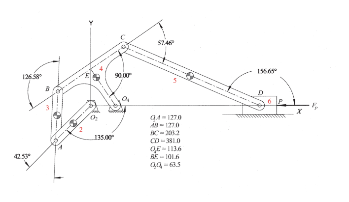 ¥
| 57.460
pu | 15665°
126.58 a 90.00° ANY
APNE
5 a [al
fh NOT — =e ~ 5
(0 a4-1270 -
J%4 5-120
( BC=2032
J 35.000 D=3810
a OE=1136
25° BE=1016
L 00-635
This is AI generated Response.
Asked by: manish kumar
Created at: 2025-09-10 06:48:32
Asked by: manish kumar
Created at: 2025-09-10 06:48:32
Final Answer:
Rendered
Raw Text
Did you like this answer?
# Explanation of the Mechanism Diagram
This is a **mechanical linkage diagram**, commonly found in the study of kinematics and mechanism design (such as for robotic arms or machinery). Let's break down its components and notation:
---
## 1. **Linkages and Joints**
- **Links:** The straight segments connecting the points, labeled with numbers (e.g., 2, 3, 4, 5, 6). Each link can rotate around its pivot points.
- **Joints:** The circles where the links connect. These are typically pinned, allowing rotation.
---
## 2. **Fixed Points**
- **O₂ and O₄:** These are fixed pivots; the rest of the mechanism moves relative to these points.
---
## 3. **Key Points/Labels**
- **A, B, C, D, E, Q, P:** These are specific points or pivots on the mechanism.
- **Q₄, Q:** These usually refer to specific positions or reference points on the mechanism.
---
## 4. **Noted Angles**
- The angles shown (e.g., 42.53°, 126.58°, etc.) indicate the instantaneous angular positions between links or with respect to a horizontal/vertical reference.
---
## 5. **Link Lengths**
On the right, the lengths between key points are given (in mm, unless otherwise noted):
| Segment | Length |
|---------|--------|
| Q₄A | 127.0 |
| AB | 127.0 |
| BC | 203.2 |
| CD | 381.0 |
| Q₄E | 113.6 |
| BE | 101.6 |
| QQ₄ | 63.5 |
---
## 6. **Motion Path**
- The end effector (point D, possibly with a gripper at P) follows a specific path as the mechanism moves.
- The angles and link lengths define the trajectory and orientation of the end effector.
---
## 7. **Purpose**
Such mechanisms are often used for:
- **Robotic arms**
- **Drawing machines**
- **Tool positioning devices**
---
## 8. **How It Works (Overview)**
1. **Input Motion:** You typically rotate one of the links attached to a fixed pivot (e.g., at O₂).
2. **Motion Transfer:** The motion is transferred through the connected links.
3. **Output Motion:** The final link (at D or P) moves along a designed path, which could be straight, circular, or complex, depending on the linkage geometry.
---
## 9. **Degrees of Freedom**
- This appears to be a planar mechanism with a single degree of freedom (one input angle determines the rest of the mechanism’s configuration).
---
## 10. **Analysis**
To analyze such a mechanism:
- Use the **link lengths** and **angles** to determine the positions of all points (e.g., using vector loops or geometric methods).
- Study how the input angle affects the output position.
---
### **Summary Table of Links and Joints**
| Link No. | Between Points | Length (mm) |
|----------|---------------|-------------|
| 2 | Q₄ - A | 127.0 |
| 3 | A - B | 127.0 |
| 4 | B - C | 203.2 |
| 5 | C - D | 381.0 |
| 6 | D - P | (not given) |
---
## **If you want to solve problems with this mechanism:**
- **Identify the input link.**
- **Use geometric or trigonometric relationships** (like the Law of Cosines/Sines) to find unknown angles or lengths.
- **Draw position vectors** for each link.
---
**If you need help with a specific calculation (e.g., finding the position of D for a given angle), let me know!**
📢 Instructions:
- Ask anything relatd to above question only.
- For new Question goto :