 VIPSolutions
Give step-by-step solution with explanation and final answer:14 Qs. For the circuit shown in Fig.5, assume that all transistor are identical and have Vy=0.7V, very high 8 and V,4= 100V. Ignore the effect of finite output resistance and find: A. Derive an expression for the current transfer ratio. [ B. For Ry=1k, Ry=2k, Ir = 2mA and ry, = 25k, find Rs and the output resistance. +8V rer | | R3 Vo hal Tr2 R1 R2 Fig.5 = =
Question:
Give step-by-step solution with explanation and final answer: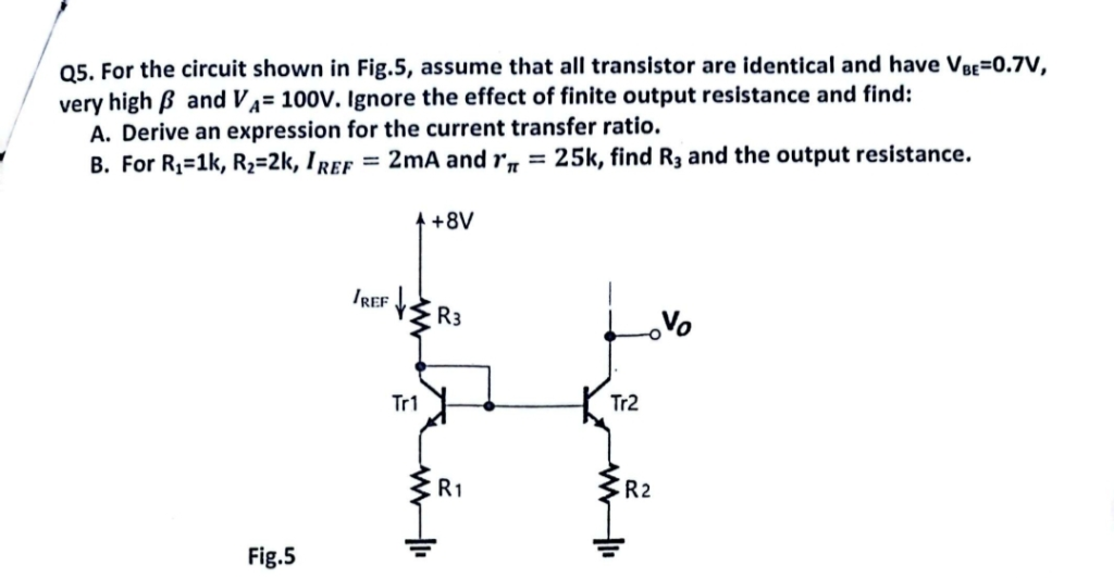 14
Qs. For the circuit shown in Fig.5, assume that all transistor are identical and have Vy=0.7V,
very high 8 and V,4= 100V. Ignore the effect of finite output resistance and find:
A. Derive an expression for the current transfer ratio.
[ B. For Ry=1k, Ry=2k, Ir = 2mA and ry, = 25k, find Rs and the output resistance.
+8V
rer | |
R3 Vo
hal Tr2
R1 R2
Fig.5 = =
This is AI generated Response.
Asked by: M Murali
Created at: 2025-08-29 08:01:03
Asked by: M Murali
Created at: 2025-08-29 08:01:03
Final Answer:
Rendered
Raw Text
Did you like this answer?
Let's solve the problem step by step:
---
## **A. Derive an expression for the current transfer ratio**
### **Step 1: Analyze the circuit**
This is a current mirror circuit using two identical NPN BJTs (Tr1 and Tr2).
- \( I_{REF} \) is the reference current through \( R_3 \) and Tr1.
- Tr2 mirrors the current, providing output at \( V_O \).
### **Step 2: Write the KVL for Tr1 and Tr2**
Since both transistors are identical and \( V_{BE} \) is the same for both,
- The voltage across \( R_1 \) and \( R_2 \) will set the emitter currents.
- Assume base currents are negligible due to high \( \beta \).
#### For **Tr1**:
\[
I_{E1} = I_{C1} + I_{B1} \approx I_{C1} \quad (\text{since } \beta \text{ is very high})
\]
\[
I_{C1} = \frac{V_{R1}}{R_1} = \frac{V_{E1}}{R_1}
\]
#### For **Tr2**:
\[
I_{C2} = \frac{V_{R2}}{R_2} = \frac{V_{E2}}{R_2}
\]
Both emitters are at the same voltage (since bases are tied together and emitters are referenced through resistors).
### **Step 3: Current Transfer Ratio**
The current mirror ratio is set by the resistor values in the emitters:
\[
\frac{I_{C2}}{I_{C1}} = \frac{V_{E2}/R_2}{V_{E1}/R_1}
\]
But \( V_{E1} = V_{E2} \) (since both emitters are at same potential),
so:
\[
\frac{I_{C2}}{I_{C1}} = \frac{R_1}{R_2}
\]
### **Step 4: Expression for Output Current**
\[
I_{OUT} = I_{C2} = I_{C1} \cdot \frac{R_1}{R_2}
\]
---
## **B. Given values, find \( R_3 \) and the output resistance**
**Given:**
- \( R_1 = 1k\Omega \)
- \( R_2 = 2k\Omega \)
- \( I_{REF} = 2\,mA \)
- \( r_\pi = 25k\Omega \)
### **Step 1: Find \( R_3 \)**
Apply KVL at the loop from +8V to ground through \( R_3 \), Tr1, and \( R_1 \):
\[
8V = I_{REF} R_3 + V_{BE} + I_{C1} R_1
\]
Since \( I_{REF} \approx I_{C1} \) (base current is negligible),
\[
8V = I_{REF} R_3 + 0.7V + I_{REF} R_1
\]
\[
I_{REF} (R_3 + R_1) = 8V - 0.7V
\]
\[
R_3 + R_1 = \frac{7.3V}{2mA} = 3650 \Omega
\]
\[
R_3 = 3650 - 1000 = 2650\Omega = 2.65k\Omega
\]
### **Step 2: Output Resistance**
Ignoring finite output resistance (as per question), output resistance is **ideally infinite**.
But if you include transistor output resistance (\( r_o \)), for a current mirror:
\[
r_{out} = r_o = \frac{V_A}{I_C}
\]
Given \( V_A = 100V \), \( I_C = 1mA \) (since \( I_{C2} = I_{REF} \cdot \frac{R_1}{R_2} = 2mA \times \frac{1}{2} = 1mA \))
\[
r_{out} = \frac{100V}{1mA} = 100k\Omega
\]
---
## **Summary of Answers**
### **A. Expression for current transfer ratio:**
\[
\boxed{\frac{I_{C2}}{I_{C1}} = \frac{R_1}{R_2}}
\]
### **B.**
\[
\boxed{R_3 = 2.65\,k\Omega}
\]
\[
\boxed{\text{Output resistance} = 100\,k\Omega}
\]
---
**Let me know if you'd like further clarification or details!**
Question:
A Give ME Explanation in 100 Words Only Theory
This is AI generated Response.
Asked by: M Murali
Created at: 2025-08-29 08:16:41
Asked by: M Murali
Created at: 2025-08-29 08:16:41
Final Answer:
Rendered
Raw Text
Did you like this answer?
The circuit is a current mirror using two identical BJTs. The reference current \(I_{REF}\) flows through resistor \(R_3\) and transistor Tr1, setting its emitter current. Since the transistors are matched with high \(\beta\), the base-emitter voltage (\(V_{BE}\)) is approximately equal, causing Tr2 to mirror the current based on the emitter resistor ratio. The current transfer ratio is determined by the ratio of emitter resistors: \(\frac{I_{OUT}}{I_{REF}} = \frac{R_1}{R_2}\). By selecting resistor values and considering transistor parameters, the circuit provides a stable current output proportional to the reference current.
Question:
B Give ME Explanation in 100 Words Only Theory
This is AI generated Response.
Asked by: M Murali
Created at: 2025-08-29 08:18:12
Asked by: M Murali
Created at: 2025-08-29 08:18:12
Final Answer:
Rendered
Raw Text
Did you like this answer?
The circuit is a simple current mirror employing two matched BJTs. The reference current \(I_{REF}\) flows through \(R_3\) and Tr1, establishing its emitter current. Due to transistor matching and high \(\beta\), both BJTs have nearly equal \(V_{BE}\), causing Tr2 to mirror the current based on the ratio of emitter resistors \(R_1\) and \(R_2\). The current transfer ratio is thus \(\frac{I_{OUT}}{I_{REF}} = \frac{R_1}{R_2}\). By choosing resistor values and considering transistor parameters like \(V_{BE}\), the circuit ensures a stable current output proportional to the reference current, useful in biasing and analog circuit applications.
📢 Instructions:
- Ask anything relatd to above question only.
- For new Question goto :