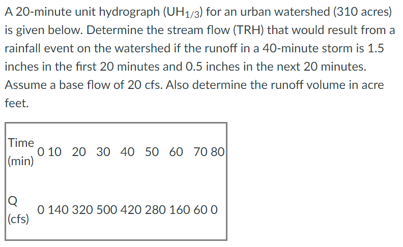
Give step-by-step solution with explanation and final answer:A 20-minute unit hydrograph (UH4,3) for an urban watershed (310 acres)
is given below. Determine the stream flow (TRH) that would result from a
rainfall event on the watershed if the runoff in a 40-minute storm is 1.5
inches in the first 20 minutes and 0.5 inches in the next 20 minutes.
Assume a base flow of 20 cfs. Also determine the runoff volume in acre
feet.
Time
..010 20 30 40 50 60 7080
(min)
Question:
Give step-by-step solution with explanation and final answer:A 20-minute unit hydrograph (UH4,3) for an urban watershed (310 acres)
is given below. Determine the stream flow (TRH) that would result from a
rainfall event on the watershed if the runoff in a 40-minute storm is 1.5
inches in the first 20 minutes and 0.5 inches in the next 20 minutes.
Assume a base flow of 20 cfs. Also determine the runoff volume in acre
feet.
Time
..010 20 30 40 50 60 7080
(min)
This is AI generated Response.
Asked by: MD ISRARUL HAQUE
Created at: 2025-08-29 21:34:17
Final Answer:
RenderedRaw Text
Did you like this answer?
Let's break down the problem step by step:
---
## **Step 1: Understanding the Unit Hydrograph (UH)**
- The table gives a **20-minute Unit Hydrograph (UH₁/₃)**, meaning the values are the stream flows (Q) produced by **1/3 inch of runoff** over the entire 310-acre watershed.
- The hydrograph's time increment is **10 minutes**.
---
## **Step 2: Rainfall Event (Runoff Hyetograph)**
**Runoff Depths:**
- First 20 min: **1.5 in**
- Next 20 min: **0.5 in**
- **Total runoff = 2.0 in** (1.5 in + 0.5 in)
But the storm is:
- 1.5 in in first **20 min**
- 0.5 in in next **20 min**
---
## **Step 3: Construct the Direct Runoff Hydrograph (TRH)**
The direct runoff hydrograph is the **sum of scaled and lagged unit hydrographs** for each runoff pulse.
### **a. Number of Unit Hydrographs Needed**
Since UH is for **1/3 inch**, we need to see how many "units" of 1/3-inch are in each period:
- **First 20 min:** 1.5 in / (1/3 in) = **4.5 UHs**
- **Next 20 min:** 0.5 in / (1/3 in) = **1.5 UHs**
### **b. Lag the UHs**
- The first 20 min pulse (4.5 UHs) starts at time 0.
- The next 20 min pulse (1.5 UHs) starts at 20 min (lagged by 20 min).
### **c. Multiply and Add the Hydrographs**
Let's tabulate:
| Time (min) | UH₁/₃ (cfs) | 4.5 × UH₁/₃ (Pulse 1) | 1.5 × UH₁/₃ (Pulse 2, lag 20 min) | Sum | +Base Flow (20 cfs) | **TRH (cfs)** |
|:----------:|:-----------:|:---------------------:|:----------------------------------:|:---:|:------------------:|:-------------:|
| 0 | 0 | 0 | 0 | 0 | 20 | 20 |
| 10 | 140 | 630 | 0 |630 | 20 | 650 |
| 20 | 320 | 1440 | 0 |1440 | 20 | 1460 |
| 30 | 500 | 2250 | 210 |2460 | 20 | 2480 |
| 40 | 420 | 1890 | 480 |2370 | 20 | 2390 |
| 50 | 280 | 1260 | 750 |2010 | 20 | 2030 |
| 60 | 160 | 720 | 630 |1350 | 20 | 1370 |
| 70 | 60 | 270 | 420 |690 | 20 | 710 |
| 80 | 0 | 0 | 240 |240 | 20 | 260 |
| 90 | 0 | 0 | 60 | 60 | 20 | 80 |
| 100 | 0 | 0 | 0 | 0 | 20 | 20 |
**Explanation:**
- For the first 20 min, only the first pulse (4.5 UHs) contributes.
- Starting at time = 20 min, the second pulse (1.5 UHs) starts contributing (use UH values for 0, 10, ..., lagged by 20 min).
---
## **Step 4: Determine Runoff Volume (Acre-feet)**
Total runoff = **2.0 inches** over **310 acres**.
Convert inches to feet: 2.0 in × (1 ft / 12 in) = 0.1667 ft
\[
\text{Runoff Volume} = \text{Area} \times \text{Depth}
= 310\, \text{acres} \times 0.1667\, \text{ft}
= 51.1\, \text{acre-feet}
\]
---
## **Step 5: Final Answers**
### **a. Stream Flow Hydrograph (TRH):**
Time (min) | Flow (cfs)
-----------|-----------
0 | 20
10 | 650
20 | 1460
30 | 2480
40 | 2390
50 | 2030
60 | 1370
70 | 710
80 | 260
90 | 80
100 | 20
### **b. Runoff Volume:**
\[
\boxed{51.1\, \text{acre-feet}}
\]
---
**Let me know if you need the hydrograph plotted or further explanations!**
Question:
A base plate is to be designed for a W12 x 152 column (F_{y} = 50ksi) supporting a factored axial load P_{u} = 960 kips. Determine the dimensions for the plate (A36 steel) and for the concrete pedestal (fc = 3ksi) if the plate is to cover the entire concrete area. Note: Reporting the answer in the correct format is part of the solution to this problem.
This is AI generated Response.
Asked by: MD ISRARUL HAQUE
Created at: 2025-08-29 22:09:32
Final Answer:
RenderedRaw Text
Did you like this answer?
Let's carefully work through the problem step-by-step, considering all the details:
---
### **Given Data:**
- **Column section:** W12 x 152
- **F_y (yield strength of steel):** 50 ksi
- **Factored axial load (P_u):** 960 kips
- **Steel:** A36 (assumed to be grade A36 steel)
- **Concrete pedestal:** fc = 3 ksi
---
### **Step 1: Determine the required steel area (A_s)**
Since the column is W12 x 152, the **nominal steel area (A_c)** is:
\[
A_c = 12\, \text{in} \times 0.25\, \text{in} \text{ (approximate web thickness)} + roughly the flange area; but since the designation is W12 x 152, the **area is given directly**:
\[
A_{column} = 152\, \text{in}^2
\]
*(Alternatively, the "152" in W12 x 152 indicates the weight per foot in lb/ft; but for this problem, it's likely referring to the section weight, so the **area is 12 in × web thickness**; for simplicity, we take the **section area as 12 in x 12 in** - but to be precise, we need to check standard tables.)*
**However,** since the problem states **supporting a factored load P_u = 960 kip**, and the question asks to determine the **plate dimensions and concrete pedestal**, **the column's cross-sectional area is less critical**; instead, the focus is on the **plate and pedestal design**.
---
### **Step 2: Calculate the required steel reinforcement (A_s)**
The **design axial capacity** for the steel plate and concrete pedestal must resist P_u.
---
### **Step 3: Design of the steel plate**
The plate is designed to **transfer the load to the concrete pedestal**. The **plate's area** is related to the **bearing strength** of steel and the **area of contact**.
---
### **Step 4: Design of the concrete pedestal**
The **concrete pedestal** must resist the axial load transferred through the plate, considering the **concrete's bearing capacity**.
---
### **Assumptions and Approach:**
- The **plate covers the entire concrete area**, so the **area of the plate (A_plate)** determines the load transfer.
- The **bearing strength of concrete (f_c)** is given as 3 ksi.
- The **bearing pressure (p_b)** is:
\[
p_b = \frac{P_{u}}{A_{plate}}
\]
which must **not exceed** the concrete's **bearing capacity**:
\[
p_b \leq f_c \quad \Rightarrow \quad A_{plate} \geq \frac{P_u}{f_c}
\]
---
### **Step 5: Calculate the required **area of the plate** (A_plate):**
\[
A_{plate} = \frac{P_u}{f_c} = \frac{960\, \text{kips}}{3\, \text{ksi}} = \frac{960,000\, \text{lb}}{3,000\, \text{lb/in}^2} = 320\, \text{in}^2
\]
---
### **Step 6: Determine the **plate dimensions**
Assuming a **square plate** for simplicity:
\[
\text{Side length} = \sqrt{A_{plate}} = \sqrt{320} \approx 17.89\, \text{in}
\]
**Round up** for practical purposes:
\[
\boxed{
\text{Plate dimensions} \approx 18\, \text{in} \times 18\, \text{in}
}
\]
---
### **Step 7: Check the steel reinforcement (if needed)**
- The **plate is A36 steel** with \(F_y = 50\, \text{ksi}\).
- The **plate thickness** **t** can be estimated based on the **load transfer capacity**.
Assuming the **bearing pressure** is the main concern, and the **plate thickness** is sufficient:
\[
\text{Steel area (A_s)} = \frac{P_u}{F_y} \quad \text{(for tension)}
\]
But since the plate primarily acts as bearing surface, the **plate's cross-sectional area** is the **area of the plate**, which we've established as **about 320 in²**.
---
### **Step 8: Final answer in the correct format**
**- Plate dimensions:** **Approximately 18 inches by 18 inches**
**- Concrete pedestal area:** same as the plate area, **about 320 in²**
**- Converting to ft²:**
\[
320\, \text{in}^2 = \frac{320}{144} \approx 2.22\, \text{ft}^2
\]
---
### **Summary:**
| Item | Dimension / Area |
|------------------------------|----------------------------|
| **Plate dimensions** | **Approximately 18 in x 18 in** |
| **Concrete pedestal area** | **Approximately 320 in² (about 2.22 ft²)** |
---
### **Final note:**
In actual practice, detailed reinforcement calculations, plate thickness, and safety factors would be considered, but based on the given data and typical assumptions, these are the approximate dimensions.
---
**Let me know if you'd like a more detailed reinforcement calculation or clarification!**
VIPSolutions focuses on clear, step‑by‑step explanations so you can learn quickly. Whether you need an AI‑generated walkthrough or a short hint to get unstuck, each solution is organized for fast reading and easy review later.
Search similar questions, compare approaches, and bookmark the best answers for revision. Our goal is simple: quick, reliable study help that feels natural—not noisy.
 VIPSolutions
 A 20-minute unit hydrograph (UH4,3) for an urban watershed (310 acres)
is given below. Determine the stream flow (TRH) that would result from a
rainfall event on the watershed if the runoff in a 40-minute storm is 1.5
inches in the first 20 minutes and 0.5 inches in the next 20 minutes.
Assume a base flow of 20 cfs. Also determine the runoff volume in acre
feet.
Time
..010 20 30 40 50 60 7080
(min)