 VIPSolutions
2. a) Calculate the speed v in the following case are (when 4; = 120cm?,4, = A; = 60cm?,Q; = 401/min) b) What is the maximum force in the extending direction, when the pump pressure is 200bar? c) What is the hydraulic power of pump d) Calculate the required radian volume of pump, when its shaft speed is 1800rev/min Ay As v A ER Q,
Question:
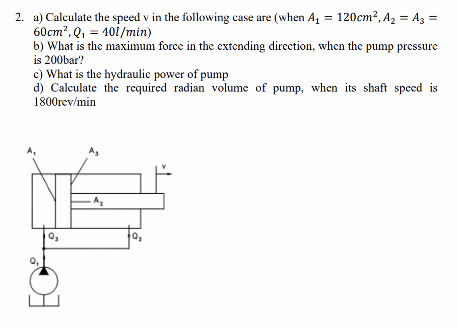 2. a) Calculate the speed v in the following case are (when 4; = 120cm?,4, = A; =
60cm?,Q; = 401/min)
b) What is the maximum force in the extending direction, when the pump pressure
is 200bar?
c) What is the hydraulic power of pump
d) Calculate the required radian volume of pump, when its shaft speed is
1800rev/min
Ay As
v
A
ER
Q,
This is AI generated Response.
Asked by: Bhukya Nagesh
Created at: 2025-10-15 00:22:35
Asked by: Bhukya Nagesh
Created at: 2025-10-15 00:22:35
Thought Process:
Rendered
Raw Text
**Analyzing hydraulic circuits**
I need to take a closer look at the hydraulic circuit shown in the diagram. There are areas labeled A1, A2, and A3, with A1 possibly being a small chamber. The arrangement seems to be a differential cylinder using a regenerative circuit, with pump Q1 flowing into one side of the cylinder. If A1 is 120 cm² and A2 and A3 are both 60 cm², I'm trying to clarify the total piston area and the extension speed formula for regenerative circuits.**Inspecting hydraulic connections**
I need to analyze the connections in this hydraulic circuit further. It looks like the rod port connects to the cap port, but the drawing shows the pump connected to Q3, which is the left lower port. The pump symbol indicates inflow Q1 going up to a line that connects to the left port of the cylinder. Then it moves from Q3 over to the right connection labeled Q2 at the rod-side port. So, it seems the pump flows Q1 up to a tee at Q3 before continuing to Q2.**Understanding pump connections**
I see that the pump flows into both Q3 and Q2 at the same time, meaning these ports are connected in parallel. This setup would create a regenerative extension since both the cap and rod sides get pump flow. However, the rod side fluid needs a place to exit, which might be back to the cap side. If the fluid is equally pressurized, the net force would relate to the difference in effective areas. Typically, a regenerative circuit uses a 3-way directional control valve to manage these fluid paths effectively.**Clarifying regenerative extension**
In regenerative extension, I understand that both ports connect to the pump. The flow from the rod side seems to go through a check valve into the cap side, but I'm unsure about that. The drawing marks Q1 as the pump output, and Q3 appears to be a port at the head end. A1 might represent a small piston area, while A2 could be the annulus area. There’s a possibility of a tandem cylinder setup, where A1 is the rear piston area, A2 is the annular area of the front piston, and A3 is for an intermediate piston. I really need to take a closer look at the drawing!**Analyzing cylinder arrangements**
Okay, here I see two pistons: A small piston labeled A1 on the left and a tubular sleeve labeled A3 on the right. Inside, A2 seems to correspond to the rod area. This could indicate a differential cylinder arrangement, where the pump flow Q1 enters at the bottom left and splits between both cavities. In regeneration, both ports connect to the pump, allowing for volume displacement and faster extension speeds. The equations all point to the necessity of precise relationships between these areas, especially as the extension speed increases with a smaller rod area.**Calculating hydraulic parameters**
From the details given, I see A1 as 120 cm², with A2 and A3 both at 60 cm². This means A2 could be the rod area and A3 the annulus, which is consistent. I need to calculate the piston extension speed using the formula v = Q1/A_rod. Given Q1 is 40 l/min, I convert that to cm³/min, resulting in 666.67 cm/min or about 0.111 m/s. Additionally, the maximum extending force at 200 bar pressure is 120 kN, while hydraulic power is around 13.3 kW with a pump displacement of approximately 22.2 cm³/rev.**Crafting hydraulic system explanation**
Let's break down the key calculations for the regenerative hydraulic system.
For part (a), the extension speed \( v \) is calculated using \( v = Q1/A_{\text{effective}} \). With \( Q1 = 40 \, \text{L/min} \) and an effective area \( A_{\text{effective}} = 60 \, \text{cm}^2 \), it converts to \( v = 0.111 \, \text{m/s} \).
For part (b), the maximum force \( F_{\text{max}} \) is \( F = P \times (A1 - A3) = 120 \, \text{kN} \).
Next, part (c) gives hydraulic power \( P_{\text{hyd}} = 13.3 \, \text{kW} \).
Finally, for part (d), the pump displacement is \( V_g = 22.2 \, \text{cm}^3/\text{rev} \). The results provide a clear overview of the system's performance.
Final Answer:
Rendered
Raw Text
Did you like this answer?
Interpretation of the circuit: the ports of the cap and rod sides are connected (regeneration). Hence the effective area in extension is the rod area:
Aeff = A1 − A3 = A2.
Given: A1 = 120 cm², A2 = A3 = 60 cm², Q1 = 40 L/min.
a) Extension speed
v = Q1/Aeff = Q1/A2
= 40,000 cm³/min ÷ 60 cm²
= 666.7 cm/min = 6.67 m/min = 0.111 m/s (≈ 111 mm/s)
b) Maximum extending force at 200 bar
Fmax = p · Aeff = p · A2
= 200 bar × 60 cm²
(1 bar on 1 cm² = 10 N)
= 200 × 60 × 10 N = 120,000 N = 120 kN
c) Hydraulic power of pump
Ph = p · Q = 200 bar × 40 L/min
= (200 × 40)/600 kW ≈ 13.3 kW
d) Required pump displacement (at 1800 rev/min)
Vg = Q/n = 40 L/min ÷ 1800 rev/min
= 0.0222 L/rev = 22.2 cm³/rev
Notes: Results assume ideal conditions (no leakage and 100% efficiencies).
📢 Instructions:
- Ask anything relatd to above question only.
- For new Question goto :