UPI. DOL SELL TUTTY ASAE BAUD TUE LEG Suaita.
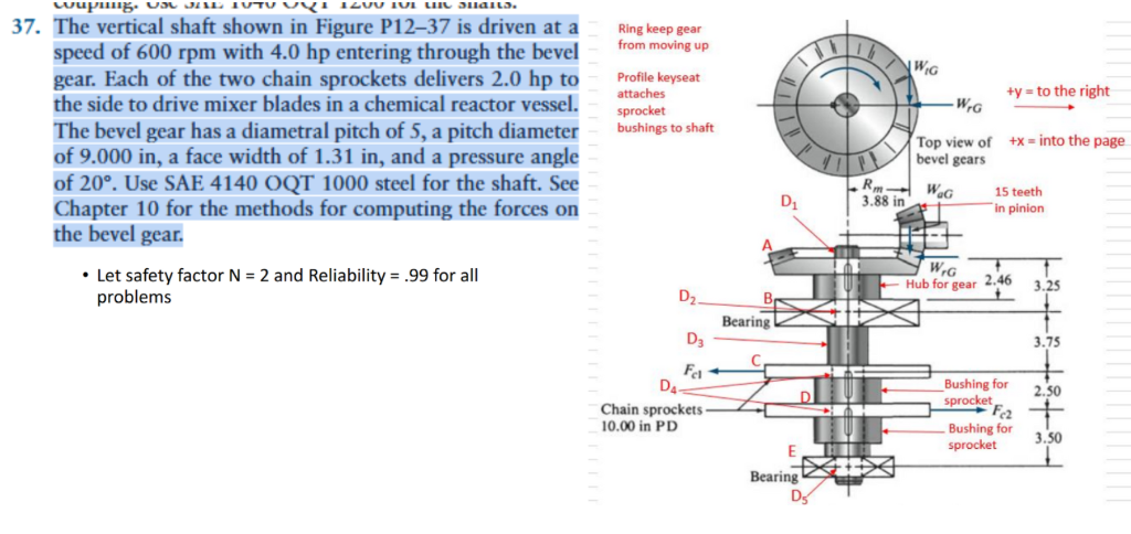
37. The vertical shaft shown in Figure P12-37 is driven ata sing eep sear
speed of 600 rpm with 4.0 hp entering through the bevel ~~ *"
Wi
gear. Each of the two chain sprockets delivers 2.0 hp to Profle eyeest .
poate +y = to the right
the side to drive mixer blades in a chemical reactor vessel. {cu we ——t
The bevel gear has a diametral pitch of 5, a pitch diameter ~~ shines osnat
Top view of +x = into the page
of 9.000 in, a face width of 1.31 in, and a pressure angle bevel gears
of 20°. Use SAE 4140 OQT 1000 steel for the shaft. See Ruel Wg 1steeth
Chapter 10 for the methods for computing the forces on Ce pinion
the bevel gear. E18]
= TT iY
+ Let safety factor N = 2 and Reliability = 99 for all Tif rise 206 30s
problems D, Br, 1
Bans > >
Question:
UPI. DOL SELL TUTTY ASAE BAUD TUE LEG Suaita.
37. The vertical shaft shown in Figure P12-37 is driven ata sing eep sear
speed of 600 rpm with 4.0 hp entering through the bevel ~~ *"
Wi
gear. Each of the two chain sprockets delivers 2.0 hp to Profle eyeest .
poate +y = to the right
the side to drive mixer blades in a chemical reactor vessel. {cu we ——t
The bevel gear has a diametral pitch of 5, a pitch diameter ~~ shines osnat
Top view of +x = into the page
of 9.000 in, a face width of 1.31 in, and a pressure angle bevel gears
of 20°. Use SAE 4140 OQT 1000 steel for the shaft. See Ruel Wg 1steeth
Chapter 10 for the methods for computing the forces on Ce pinion
the bevel gear. E18]
= TT iY
+ Let safety factor N = 2 and Reliability = 99 for all Tif rise 206 30s
problems D, Br, 1
Bans > >
This is AI generated Response.
Asked by: Govind Prajapati
Created at: 2025-07-18 00:22:01
Final Answer:
RenderedRaw Text
Did you like this answer?
Let's break down the given **problem 37** and the provided **figure** step by step:
---
### **Given Data:**
- **Vertical shaft speed:** 600 rpm
- **Power input:** 4.0 hp (entering through bevel gear)
- **Each chain sprocket delivers:** 2.0 hp (to the side for mixer blades)
- **Bevel Gear:**
- **Diametral pitch:** 5
- **Pitch diameter:** 9.000 in
- **Face width:** 1.31 in
- **Pressure angle:** 20°
- **Material:** SAE 4140 OQT 1000 steel for the shaft
- **Safety Factor:** N = 2
- **Reliability:** 0.99
---
### **What You Need to Do:**
1. **Compute the forces on the bevel gear** (using Chapter 10 methods).
2. **Analyze the shaft** for strength and reliability with the given factor of safety.
3. **Design/check the shaft** for the loading from the bevel gear and sprockets.
---
## **Step 1: Power and Torque Calculation**
**Power (P):** \( 4.0 \text{ hp} \)
**Speed (n):** \( 600 \text{ rpm} \)
Convert power to watts:
\[
P = 4.0 \text{ hp} \times 746 = 2984 \text{ W}
\]
**Torque (T):**
\[
T = \frac{63025 \times P_{\text{hp}}}{n}
\]
\[
T = \frac{63025 \times 4}{600} = 420.2 \text{ in-lb}
\]
---
## **Step 2: Forces on Bevel Gear**
You need to find the **tangential (W_T), radial (W_R), and axial (W_A) forces** on the bevel gear.
- **Pitch diameter (d):** 9.0 in
\[
W_T = \frac{2T}{d}
\]
\[
W_T = \frac{2 \times 420.2}{9} = 93.4 \text{ lb}
\]
- **Pressure angle (\(\phi\)):** 20°
- **Pitch angle (\(\theta\)):** For a 90° bevel gear set, pinion and gear have pitch angles of 45°
- **Axial force:** \( W_A = W_T \tan(\theta) \)
- **Radial force:** \( W_R = W_T \tan(\phi) \cos(\theta) \)
\[
W_A = W_T \tan(45°) = 93.4 \times 1 = 93.4 \text{ lb}
\]
\[
W_R = W_T \tan(20°) \cos(45°)
\]
\[
= 93.4 \times 0.3640 \times 0.7071 = 24.0 \text{ lb}
\]
---
## **Step 3: Sprocket Loads**
Each sprocket delivers 2.0 hp.
\[
T_{\text{sprocket}} = \frac{63025 \times 2}{600} = 210.1 \text{ in-lb}
\]
\[
W_{\text{chain}} = \frac{2 \times 210.1}{10} = 42.0 \text{ lb}
\]
---
## **Step 4: Load Distribution and Shaft Analysis**
- The figure shows locations for bearings and points where loads are applied (bevel gear, chain sprockets).
- Use the calculated forces at locations A, C, D (where gear and sprocket loads are applied).
- Draw the free body diagram and calculate reaction forces at the bearings.
- Use the **shaft design criteria** (bending, torsion, combined stress) and apply the safety factor \( N = 2 \) and reliability correction.
---
## **Step 5: Material Strength**
- SAE 4140 OQT 1000 steel properties (approximate):
- Yield strength, \( S_y \) ≈ 90 ksi
- Ultimate strength, \( S_u \) ≈ 115 ksi
---
### **Summary of Calculated Forces:**
- **Bevel Gear:**
- Tangential: **93.4 lb**
- Axial: **93.4 lb**
- Radial: **24.0 lb**
- **Each Sprocket:** **42.0 lb** tangential chain force
---
### **Next Steps**
1. **Draw the complete force diagram on the shaft.**
2. **Calculate the bending moment and torsional moment at each critical section.**
3. **Check the shaft for combined stresses using the selected factor of safety and reliability.**
If you need the full shaft design and stress calculations, let me know and I can walk you through each step in detail!
VIPSolutions focuses on clear, step‑by‑step explanations so you can learn quickly. Whether you need an AI‑generated walkthrough or a short hint to get unstuck, each solution is organized for fast reading and easy review later.
Search similar questions, compare approaches, and bookmark the best answers for revision. Our goal is simple: quick, reliable study help that feels natural—not noisy.
 VIPSolutions
 UPI. DOL SELL TUTTY ASAE BAUD TUE LEG Suaita.
37. The vertical shaft shown in Figure P12-37 is driven ata sing eep sear
speed of 600 rpm with 4.0 hp entering through the bevel ~~ *"
Wi
gear. Each of the two chain sprockets delivers 2.0 hp to Profle eyeest .
poate +y = to the right
the side to drive mixer blades in a chemical reactor vessel. {cu we ——t
The bevel gear has a diametral pitch of 5, a pitch diameter ~~ shines osnat
Top view of +x = into the page
of 9.000 in, a face width of 1.31 in, and a pressure angle bevel gears
of 20°. Use SAE 4140 OQT 1000 steel for the shaft. See Ruel Wg 1steeth
Chapter 10 for the methods for computing the forces on Ce pinion
the bevel gear. E18]
= TT iY
+ Let safety factor N = 2 and Reliability = 99 for all Tif rise 206 30s
problems D, Br, 1
Bans > >