VIPSolutions logo ✨ VIPSolutions

To prevent aseptic loosening in total knee replacements due to chronic and advanced osteoarthritis (OA) in the distal femur of Mr. David's, the following students Obi, Jessica, Sam, and Icool in our BME 2502 course recommended additional layer of polyethylene/polycarbonate spacer. If the state of stress in the element of his femur is represented in Figure 1 below. To enable the design of the robust femoral-knee implant replacement, the following must be determined: | 40 MPa LL _ = 35MPa Ir Lo a a | 60 MPa = —_— — SL / 5 >. i, 3 Conponenc Figure 1 a. Calculate the equivalent state of stress on an element at the same point oriented 30° counterclockwise with respect to the element shown. Sketch the results on the rotated element. b. Calculate the state of stress that represents the principal stresses, the angle of orientation, and sketch the results on the updated rotated element. c. Calculate the state of stress that represents the maximum in-plane shear stress (Tmaxin-plane) and associated average normal stress, the angle of orientation, and sketch the results on the updated rotated element. d. Quickly sketch the Mohr’s circle (MC) for the original state of stress with © and o axes for the given stress element above. From the MC sketch above determine and verify the location on the circle for the max shear stress and principal stresses.

Question:
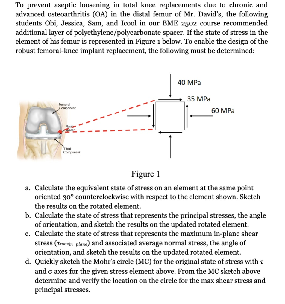
Uploaded ImageTo prevent aseptic loosening in total knee replacements due to chronic and advanced osteoarthritis (OA) in the distal femur of Mr. David's, the following students Obi, Jessica, Sam, and Icool in our BME 2502 course recommended additional layer of polyethylene/polycarbonate spacer. If the state of stress in the element of his femur is represented in Figure 1 below. To enable the design of the robust femoral-knee implant replacement, the following must be determined: | 40 MPa LL _ = 35MPa Ir Lo a a | 60 MPa = —_— — SL / 5 >. i, 3 Conponenc Figure 1 a. Calculate the equivalent state of stress on an element at the same point oriented 30° counterclockwise with respect to the element shown. Sketch the results on the rotated element. b. Calculate the state of stress that represents the principal stresses, the angle of orientation, and sketch the results on the updated rotated element. c. Calculate the state of stress that represents the maximum in-plane shear stress (Tmaxin-plane) and associated average normal stress, the angle of orientation, and sketch the results on the updated rotated element. d. Quickly sketch the Mohr’s circle (MC) for the original state of stress with © and o axes for the given stress element above. From the MC sketch above determine and verify the location on the circle for the max shear stress and principal stresses.

This is AI generated Response.
Asked by: Satish Reddy
Created at: 2025-06-28 05:53:30

Final Answer:

Rendered Raw Text
Did you like this answer?
Let's break down how to approach each part of this problem step by step, using the values from Figure 1. ### **Given:** - Stresses on the element: - \(\sigma_x = 60\) MPa (horizontal, right) - \(\sigma_y = 35\) MPa (vertical, up) - \(\tau_{xy} = 40\) MPa (shear, assume positive in the direction shown) --- ### **a. State of Stress on an Element Rotated 30° Counterclockwise** The stress transformation equations for a rotated element are: \[ \sigma_x' = \frac{\sigma_x + \sigma_y}{2} + \frac{\sigma_x - \sigma_y}{2} \cos 2\theta + \tau_{xy} \sin 2\theta \] \[ \sigma_y' = \frac{\sigma_x + \sigma_y}{2} - \frac{\sigma_x - \sigma_y}{2} \cos 2\theta - \tau_{xy} \sin 2\theta \] \[ \tau_{x'y'} = -\frac{\sigma_x - \sigma_y}{2} \sin 2\theta + \tau_{xy} \cos 2\theta \] Where \(\theta = 30^\circ\). - \(\cos 2\theta = \cos 60^\circ = 0.5\) - \(\sin 2\theta = \sin 60^\circ = 0.866\) Substitute values: - \(\sigma_x = 60\) MPa - \(\sigma_y = 35\) MPa - \(\tau_{xy} = 40\) MPa **Calculations:** \[ \frac{\sigma_x + \sigma_y}{2} = \frac{60 + 35}{2} = 47.5 \text{ MPa} \] \[ \frac{\sigma_x - \sigma_y}{2} = \frac{60 - 35}{2} = 12.5 \text{ MPa} \] Now: \[ \sigma_x' = 47.5 + (12.5)(0.5) + (40)(0.866) \] \[ = 47.5 + 6.25 + 34.64 = 88.39 \text{ MPa} \] \[ \sigma_y' = 47.5 - (12.5)(0.5) - (40)(0.866) \] \[ = 47.5 - 6.25 - 34.64 = 6.61 \text{ MPa} \] \[ \tau_{x'y'} = - (12.5)(0.866) + 40(0.5) \] \[ = -10.825 + 20 = 9.18 \text{ MPa} \] **Sketch**: Draw a rotated element (30° CCW from the original), label the new faces with \(\sigma_x' = 88.39\) MPa, \(\sigma_y' = 6.61\) MPa, and \(\tau_{x'y'} = 9.18\) MPa. --- ### **b. Principal Stresses and Orientation** Principal stresses (\(\sigma_1, \sigma_2\)) are given by: \[ \sigma_{1,2} = \frac{\sigma_x + \sigma_y}{2} \pm \sqrt{\left( \frac{\sigma_x - \sigma_y}{2} \right)^2 + \tau_{xy}^2} \] \[ \sqrt{(12.5)^2 + (40)^2} = \sqrt{156.25 + 1600} = \sqrt{1756.25} = 41.92 \] So, \[ \sigma_1 = 47.5 + 41.92 = 89.42 \text{ MPa} \] \[ \sigma_2 = 47.5 - 41.92 = 5.58 \text{ MPa} \] Angle \(\theta_p\) to principal planes (from x-axis): \[ \tan 2\theta_p = \frac{2\tau_{xy}}{\sigma_x - \sigma_y} = \frac{2 \times 40}{60 - 35} = \frac{80}{25} = 3.2 \] \[ 2\theta_p = \tan^{-1}(3.2) = 72.65^\circ \] \[ \theta_p = 36.33^\circ \] **Sketch**: Draw the element rotated by \(\theta_p = 36.33^\circ\), label \(\sigma_1 = 89.42\) MPa, \(\sigma_2 = 5.58\) MPa, and no shear. --- ### **c. Maximum In-Plane Shear Stress** Maximum in-plane shear stress (\(\tau_{max}\)): \[ \tau_{max} = \sqrt{ \left( \frac{\sigma_x - \sigma_y}{2} \right)^2 + \tau_{xy}^2 } = 41.92 \text{ MPa} \] Associated average normal stress (\(\sigma_{avg}\)): \[ \sigma_{avg} = \frac{\sigma_x + \sigma_y}{2} = 47.5 \text{ MPa} \] Orientation angle to max shear: \[ \theta_s = \theta_p + 45^\circ = 36.33^\circ + 45^\circ = 81.33^\circ \] **Sketch**: Draw the element rotated by \(81.33^\circ\), label shear \(\tau_{max} = 41.92\) MPa, and normal stress \(\sigma_{avg} = 47.5\) MPa. --- ### **d. Mohr’s Circle** - Center: (\(\sigma_{avg}\), 0) = (47.5 MPa, 0) - Radius: \(\tau_{max} = 41.92\) MPa **Key Points:** - Principal stresses: \(89.42\) MPa, \(5.58\) MPa (on \(\sigma\) axis) - Max shear: \((47.5, 41.92)\), \((47.5, -41.92)\) **Quick Sketch:** 1. Draw the \(\sigma\)-axis (horizontal), \(\tau\)-axis (vertical). 2. Mark the center at (47.5, 0). 3. Plot principal stresses at (89.42, 0) and (5.58, 0). 4. Mark max shear at (47.5, ±41.92). --- ## **Summary Table** | Parameter | Value | |-----------------------------------|-----------------| | Rotated Stress (\(\sigma_x'\)) | 88.39 MPa | | Rotated Stress (\(\sigma_y'\)) | 6.61 MPa | | Rotated Shear (\(\tau_{x'y'}\)) | 9.18 MPa | | Principal Stress (\(\sigma_1\)) | 89.42 MPa | | Principal Stress (\(\sigma_2\)) | 5.58 MPa | | Principal Angle (\(\theta_p\)) | 36.33° | | Max Shear (\(\tau_{max}\)) | 41.92 MPa | | Avg Normal (\(\sigma_{avg}\)) | 47.5 MPa | | Shear Angle (\(\theta_s\)) | 81.33° | --- If you need the explicit sketches, let me know and I can describe or create them!

📢 Instructions:

  • Ask anything relatd to above question only.
  • For new Question goto :

Study Help, Fast Answers

VIPSolutions focuses on clear, step‑by‑step explanations so you can learn quickly. Whether you need an AI‑generated walkthrough or a short hint to get unstuck, each solution is organized for fast reading and easy review later.

Search similar questions, compare approaches, and bookmark the best answers for revision. Our goal is simple: quick, reliable study help that feels natural—not noisy.