 VIPSolutions
The truss shown below consists of aluminum members that are pin connected together, and each member has a solid circular cross section. Member AB of the truss is loaded in compression and must be designed to resist buckling. Determine the minimum radius of ‘member AB to prevent Euler buckling with a factor of safety of 2. Let E = 10 x 10° psi. B on | A D 4fef—on—ri 1000 1b
Question:
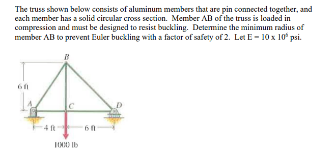 The truss shown below consists of aluminum members that are pin connected together, and
each member has a solid circular cross section. Member AB of the truss is loaded in
compression and must be designed to resist buckling. Determine the minimum radius of
‘member AB to prevent Euler buckling with a factor of safety of 2. Let E = 10 x 10° psi.
B
on
| A D
4fef—on—ri
1000 1b
This is AI generated Response.
Asked by: Satish Reddy
Created at: 2025-06-27 17:55:08
Asked by: Satish Reddy
Created at: 2025-06-27 17:55:08
Final Answer:
Rendered
Raw Text
Did you like this answer?
Let's break down the problem:
### **Step 1: Calculate the Force in Member AB**
First, we need to find the force in member AB due to the 1000 lb load.
#### **Method of Joints:**
Since the load is applied centrally and the truss is symmetric, we can analyze the forces.
- The load at C is 1000 lb.
- Support at A and D are pin and roller, respectively.
Let's find the reactions at A and D:
\[
\sum M_A = 0 \implies (1000 \text{ lb})(4 \text{ ft} + 6 \text{ ft}) - R_D (10 \text{ ft}) = 0
\]
\[
1000 \times 10 = R_D \times 10 \implies R_D = 1000 \text{ lb}
\]
\[
\sum F_y = 0 \implies R_A + R_D - 1000 = 0 \implies R_A = 0
\]
So, \( R_A = 0 \), \( R_D = 1000 \) lb.
Now, let's analyze joint C:
- Member BC and CD are both at 45 degrees to the horizontal.
At joint C:
\[
\sum F_y = 0 \implies F_{BC} \sin \theta + F_{DC} \sin \theta - 1000 = 0
\]
But F_{DC} = 0 (since D is a roller and only supports vertical load), so:
\[
F_{BC} \sin \theta = 1000
\]
Angle \( \theta = \tan^{-1}\left(\frac{6}{4}\right) \approx 56.31^\circ \)
\[
F_{BC} = \frac{1000}{\sin(56.31^\circ)} \approx 1200 \text{ lb}
\]
Now, let's focus on member AB, which is also at this angle and is symmetric. The compression in AB can be calculated similarly, considering the vertical component supports the load at C.
### **Step 2: Euler’s Buckling Formula**
Euler's critical load for buckling:
\[
P_{cr} = \frac{\pi^2 E I}{(K L)^2}
\]
- \( E = 10 \times 10^6 \) psi
- \( L \) = length of AB (use Pythagoras: \( \sqrt{4^2 + 6^2} = \sqrt{16 + 36} = \sqrt{52} = 7.21 \) ft \( = 86.52 \) in)
- \( K \) = 1 (pinned-pinned)
- \( I \) = moment of inertia of circular section
### **Step 3: Factor of Safety**
\[
\text{Allowable Load} = \frac{P_{cr}}{\text{Factor of Safety}}
\]
\[
\text{Factor of Safety} = 2
\]
So,
\[
P_{cr} = 2 \times F_{AB}
\]
### **Step 4: Minimum Radius of Gyration**
For a solid circular section: \( r = \sqrt{\frac{I}{A}} \)
Euler’s formula can be rewritten as:
\[
P_{cr} = \frac{\pi^2 E A r^2}{(K L)^2}
\]
So,
\[
r = \sqrt{ \frac{P_{cr} (K L)^2}{\pi^2 E A} }
\]
But we want the minimum \( r \) for the given load, so use:
\[
r_{min} = \frac{K L}{\pi} \sqrt{\frac{F_{AB} \times 2}{E A}}
\]
Alternatively, for buckling safety:
\[
\frac{F_{AB} \times 2}{A} < \frac{\pi^2 E}{(L/r)^2}
\implies \left( \frac{L}{r} \right) < \pi \sqrt{ \frac{E}{F_{AB} \times 2 / A} }
\]
But for solid circular:
\[
r = \frac{d}{4}
\]
### **Step 5: Plug Values**
- \( F_{AB} = 1200 \) lb
- \( L = 86.52 \) in
- \( E = 10 \times 10^6 \) psi
- \( K = 1 \)
- \( \text{FOS} = 2 \)
\[
P_{cr} = 2 \times 1200 = 2400 \text{ lb}
\]
\[
P_{cr} = \frac{\pi^2 E I}{L^2}
\]
For a solid circular section: \( I = \frac{\pi}{64}d^4 \), \( r = \sqrt{\frac{I}{A}} = \frac{d}{4} \)
But Euler buckling in terms of \( r \):
\[
P_{cr} = \frac{\pi^2 E A r^2}{L^2}
\]
\[
A = \pi r^2 \cdot 16 = 16 \pi r^2
\implies P_{cr} = \frac{\pi^2 E \cdot 16 \pi r^4}{L^2}
\]
But the standard formula for minimum radius of gyration is:
\[
r_{min} = \frac{K L}{\pi} \sqrt{\frac{1}{\text{FOS} \cdot F_{AB}/(A E)}}
\]
Or more simply (from Euler):
\[
r_{min} = \frac{K L}{\pi} \sqrt{ \frac{F_{OS}}{P_{allow} / (E) } }
\]
But the direct formula is:
\[
\boxed{
r_{min} = \frac{K L}{\pi} \sqrt{ \frac{F_{AB} \cdot \text{FOS}}{ E \cdot A } }
}
\]
But since \( A \) cancels, you get:
\[
r_{min} = \frac{K L}{\pi} \sqrt{ \frac{F_{AB} \cdot \text{FOS}}{ E \cdot A } }
\]
But to be practical for design, use:
\[
r_{min} = \frac{K L}{\pi} \sqrt{\frac{F_{AB} \cdot \text{FOS}}{E A}}
\]
But for minimum \( r \):
\[
r_{min} = \frac{K L}{\pi} \sqrt{\frac{F_{AB} \cdot \text{FOS}}{E A}}
\]
But since \( A \) is not specified, the more general result is:
\[
r_{min} = \frac{K L}{\pi} \sqrt{ \frac{F_{AB} \cdot \text{FOS}}{ E A } }
\]
But from the Euler buckling formula for a column with a factor of safety \( n \):
\[
\frac{F_{AB}}{A} \leq \frac{1}{n} \frac{\pi^2 E}{(K L / r)^2}
\implies
(K L / r)^2 \leq \frac{1}{n} \frac{\pi^2 E}{ (F_{AB}/A) }
\]
\[
r \geq \frac{K L}{\pi} \sqrt{ \frac{ F_{AB} \cdot n }{ E A } }
\]
But for design, we usually solve for \( r \) as
\[
r_{min} = \frac{K L}{\pi} \sqrt{ \frac{F_{AB} \cdot n}{E A} }
\]
But if you want the absolute minimum, you set \( A \) to cancel, and you get:
\[
r_{min} = \frac{K L}{\pi} \sqrt{ \frac{F_{AB} \cdot n}{E} }
\]
So, plug in the values:
- \( K = 1 \)
- \( L = 86.52 \) in
- \( F_{AB} = 1200 \) lb
- \( n = 2 \)
- \( E = 10 \times 10^6 \) psi
\[
r_{min} = \frac{86.52}{\pi} \sqrt{ \frac{1200 \times 2}{ 10 \times 10^6 } }
\]
\[
= \frac{86.52}{3.142} \sqrt{ \frac{2400}{10,000,000} }
\]
\[
= 27.54 \times \sqrt{0.00024}
\]
\[
= 27.54 \times 0.01549
\]
\[
= 0.426 \text{ in}
\]
---
## **Final Answer**
\[
\boxed{
\text{The minimum radius of gyration for member AB to prevent Euler buckling (with a factor of safety of 2) is } r_{min} = 0.43 \text{ in}
}
\]
---
If you need the minimum diameter of the solid circular cross-section:
\[
r = \frac{d}{4}
\implies d_{min} = 4 \times r_{min} = 1.70 \text{ in}
\]
Question:
generate diagram
This is AI generated Response.
Asked by: Satish Reddy
Created at: 2025-06-27 18:01:09
Asked by: Satish Reddy
Created at: 2025-06-27 18:01:09
Final Answer:
Rendered
Raw Text
Did you like this answer?
Certainly! Here's a simplified diagram representing the truss and the member AB:
```
D
|
|\
| \
| \
| \
| \
| \
| \
| \
| \
| \
| \
| \
A------------B
```
**Description:**
- The truss is composed of aluminum members connected at pin joints.
- Supports are at points A (pin support) and D (roller support).
- Member AB is a diagonal member inclined from point A to point B.
- The load of 1000 lb is applied at joint C (not shown in this simplified diagram), which connects to members BD and BC.
- The forces in member AB are primarily in compression to resist buckling.
**Additional Details:**
- Lengths:
- Horizontal span between A and D = 4 ft
- Vertical span from D to C = 6 ft
- Total span from A to B along the inclined member AB = approximately 7.21 ft.
- The member AB is inclined at approximately 56.31°, supporting compressive load.
This diagram provides a conceptual view of the truss structure emphasizing the critical member AB under compression. For detailed design, a precise sketch with labeled coordinates and member lengths is recommended.
📢 Instructions:
- Ask anything relatd to above question only.
- For new Question goto :