 VIPSolutions
Draw the Shear-Force and Bending-Moment diagrams for the simply supported beam below. 100 lb/ft A B Ls o— 80 1b
Question:
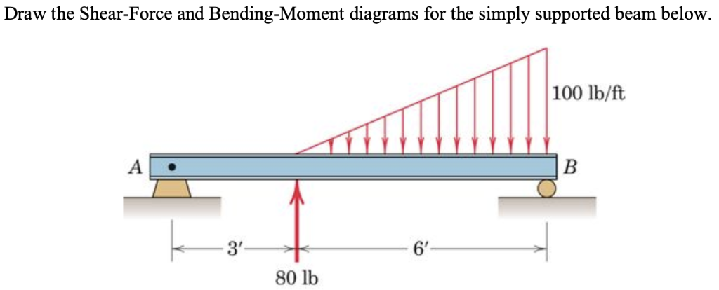 Draw the Shear-Force and Bending-Moment diagrams for the simply supported beam below.
100 lb/ft
A B
Ls o—
80 1b
This is AI generated Response.
Asked by: Bblue
Created at: 2025-07-26 11:05:14
Asked by: Bblue
Created at: 2025-07-26 11:05:14
Final Answer:
Rendered
Raw Text
Did you like this answer?
Let's walk through the process step by step:
### 1. **Identify the Loads and Reactions**
- **Point Load:** 80 lb at 3 ft from A.
- **Distributed Load:** Triangular, starting from 0 lb/ft at 3 ft from A, up to 100 lb/ft at B (9 ft from A).
### 2. **Calculate Support Reactions**
#### **a. Equivalent Load of the Triangular Distributed Load**
- **Base:** 6 ft (from 3 ft to 9 ft)
- **Height:** 100 lb/ft
- **Area (Total Load):**
\[
W = \frac{1}{2} \times 6\, \text{ft} \times 100\, \frac{\text{lb}}{\text{ft}} = 300\, \text{lb}
\]
- **Location:** From the left of the triangle (at 3 ft from A), the centroid is at \( \frac{1}{3} \) the base from the larger end (B), so:
- Distance from B: \( \frac{1}{3} \times 6 = 2\, \text{ft} \)
- Distance from A: \( 9 - 2 = 7\, \text{ft} \)
#### **b. Take Moments About A**
Let \( R_A \) and \( R_B \) be the reactions at A and B.
Sum of moments about A:
\[
R_B \times 9 - 80 \times 3 - 300 \times 7 = 0
\]
\[
R_B \times 9 = 240 + 2100 = 2340
\]
\[
R_B = \frac{2340}{9} = 260\, \text{lb}
\]
Sum of vertical forces:
\[
R_A + R_B = 80 + 300 \implies R_A = 380 - 260 = 120\, \text{lb}
\]
---
### 3. **Shear Force Diagram (SFD)**
- **From A to 3 ft:** Shear is \( +120 \) lb (no load).
- **At 3 ft:** Drop by 80 lb (point load): \( 120 - 80 = 40 \) lb.
- **From 3 ft to 9 ft:** The triangular load increases linearly:
- Shear at 9 ft:
\[
V_{9} = 40 - \text{Area under triangular load} = 40 - 300 = -260\, \text{lb}
\]
- **At B:** Shear jumps up by reaction at B (\(+260\) lb), ending at 0.
---
### 4. **Bending Moment Diagram (BMD)**
- **At A (x=0):** \( M_A = 0 \)
- **From A to 3 ft:** Linear increase (area under shear diagram):
\[
M_{3} = 120 \times 3 = 360\, \text{lb}\cdot\text{ft}
\]
- **At 3 ft:** Jump in shear (not moment), then from 3 to 9 ft, area under the shear curve (which reduces parabolically due to the triangular load).
#### **Between 3 ft and 9 ft:**
Let \( x \) be distance from A (\( 3 \leq x \leq 9 \)):
- Shear at any \( x \):
\[
V(x) = 40 - \frac{1}{2} \times (x-3) \times \frac{100}{6} \times (x-3)
\]
But for clarity, integrate the triangular load:
The intensity at a distance \( x \) from A is:
\[
w(x) = \frac{100}{6}(x-3)\ \text{lb/ft}
\]
So, the total load from 3 to \( x \) is:
\[
W(x) = \frac{1}{2}(x-3)w(x) = \frac{1}{2}(x-3)\frac{100}{6}(x-3) = \frac{50}{6}(x-3)^2
\]
Shear at \( x \) (for \( x > 3 \)):
\[
V(x) = 40 - \frac{50}{6}(x-3)^2
\]
Bending moment at \( x \):
\[
M(x) = M_3 + \int_{3}^{x} V(x) dx
\]
\[
M(x) = 360 + \int_{3}^{x} \left[40 - \frac{50}{6}(x-3)^2 \right] dx
\]
\[
= 360 + 40(x-3) - \frac{50}{18}(x-3)^3
\]
- **At B (x = 9):**
\[
M_{B} = 360 + 40(6) - \frac{50}{18}(6)^3 = 360 + 240 - \frac{50}{18}(216)
\]
\[
= 600 - 600 = 0
\]
(As expected at the simple support.)
---
### 5. **Diagrams**
#### **Shear Force Diagram (SFD):**
- Horizontal line at \( +120 \) lb from A to 3 ft.
- Drop to \( +40 \) lb at 3 ft.
- Parabolic decrease to \( -260 \) lb at B (9 ft).
- Jump to 0 at B.
#### **Bending Moment Diagram (BMD):**
- Linear increase from 0 to 360 lb·ft from A to 3 ft.
- Then a cubic curve, peaking before B and dropping back to 0 at B.
---
### 6. **Sketch**
#### **SFD:**
```
| ________
| |
| |____________
| / \
|_____/ \________
A 3' 9' B
```
#### **BMD:**
```
|
| /\
| / \
| / \
|_____/ \_______
A 3' 9' B
```
*(The actual curve from 3' to 9' is cubic, peaking after 3' and returning to 0 at 9')*
---
If you need the diagrams plotted, let me know!
📢 Instructions:
- Ask anything relatd to above question only.
- For new Question goto :