 VIPSolutions
2.4 Build the following emitter-follower circuit that controls the speed of your one of your car motors based on the light in- tensity shining on the CDS cell. Use the TIP120 power transistor from exercise 2.3. Your car should spin on the ground at a speed that depends on the light shining on the CDS cell. (The lower node of the 10K resistor should be ground.) +6 Reos +6 10K
Question:
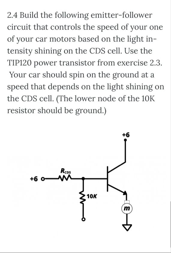 2.4 Build the following emitter-follower
circuit that controls the speed of your one
of your car motors based on the light in-
tensity shining on the CDS cell. Use the
TIP120 power transistor from exercise 2.3.
Your car should spin on the ground at a
speed that depends on the light shining on
the CDS cell. (The lower node of the 10K
resistor should be ground.)
+6
Reos
+6
10K
This is AI generated Response.
Asked by: ARJUN
Created at: 2025-10-20 00:22:23
Asked by: ARJUN
Created at: 2025-10-20 00:22:23
Final Answer:
Rendered
Raw Text
Did you like this answer?
Here's a overview and guidance for the emitter-f circuit described:
Circuit Objective
Control the speed your car motor on the light intensity a CDS cell- Use the120 power transistor exercise 23.
- circuit should spin the motor at a proportional to light.
# Components
- TIP Darlington transistor
- CDS cell (photoresistor)
- 10kΩ resistor
- Power transistor (TIP120)
- Power supply (+6V)
- Motor (represented as \(m\))
- Ground connection
# Circuit Description
- The CDS cell is connected in series with a resistor (\(R_{CDS}\)) to form a voltage divider.
- The junction between the CDS cell and resistor connects to the base of the TIP120 transistor.
- The emitter of the TIP120 connects to the motor.
- The collector of the TIP120 connects to +6V.
- The other terminal of the motor connects to ground.
# Working Principle
- Light intensity affects the CDS cell resistance, changing the voltage at the transistor's base.
- Increased light results in a higher base voltage, turning the TIP120 on more strongly.
- This causes more current through the motor, increasing its speed.
- Adjusting the light on the CDS controls the motor speed.
# Important Notes
- Ensure the lower node of the 10K resistor is connected to ground.
- The circuit uses the TIP120's Darlington configuration for high current control.
- Properly connect the power supply and verify component ratings.
Would you like a detailed schematic diagram or step-by-step assembly instructions?
📢 Instructions:
- Ask anything relatd to above question only.
- For new Question goto :